
Data Sheet


WPMDH1152401 / 171012402
MagI
3
C Power Module
VDRM – Variable Step Down Regulator Module
we-online.com Würth Elektronik eiSos GmbH & Co. KG – Data Sheet Rev. 2.0
© December 2017
24/54
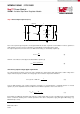
The second contributing factor is the voltage drop due to the discharge of the output capacitor. In order to estimate this
contribution, the behavior of the inductor current during the transient should be analyzed (see picture below, ESR
contribution neglected).
At the transition, the device tries to reach the new steady state as fast as possible by increasing the inductor current. This
can be achieved only by modulating the off-time t
OFF
since the on-time is fixed and defined by R
ON
. The device has a
minimum t
OFF
(t
OFF-MIN
= 260ns typ.). Therefore, as long as the new steady state is not achieved, the inductor current
increases by performing consecutive cycles of t
ON
and t
OFF-MIN
. During the transition to the new output current, the load
demand is supported by the energy stored in the output capacitor. For that reason, the output voltage drops until the
average inductor current reaches the new output current. The time for reaching this condition (t
d
) can be calculated as
follows:
t
d
=
(∆I
OUT
+
∆I
L
2
)∙L∙(t
ON
+t
OFF-MIN
)
V
IN
∙t
ON
-V
OUT
∙(t
ON
+t
OFF-MIN
)
(14)
The t
d
calculated above represents the worst case, i.e. it is supposed that the load transient occurs when the inductor
current has its minimum value (
.
The selection of the C
OUT
is related to the t
d
as well as to the current step ∆I
OUT
and the max allowed voltage drop ∆V
OUT
, as
shown by the following equation:
C
OUT
≥
(∆I
OUT
+
∆I
L
2
)∙t
d
2∙∆V
OUT
(15)
0
0,5
1
1,5
2
2,5
3
-200
-150
-100
-50
0
50
100
150
200
I
L
V
OUT
t
ON
t
OFFmin
LOAD
TRANSITION
t
d
I
OUT1
I
OUT2
∆V
OUT
t
I
L
, V
OUT