
Data Sheet


WPMDH1152401 / 171012402
MagI
3
C Power Module
VDRM – Variable Step Down Regulator Module
we-online.com Würth Elektronik eiSos GmbH & Co. KG – Data Sheet Rev. 2.0
© December 2017
25/54
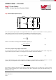
The same equation can be used for calculating the minimum required capacitance for an output current transition from high
to low (see picture below). Since the inductor current must reach the new steady state with a lower value than before, there
is no need to trigger a new on-time cycle. Instead, the off-time is extended until the average inductor current reaches the
new load current value. The excess of current during this time charges the output capacitor. This causes the output voltage
to increase and an overshoot occurs. The time t
d
for reaching the new steady state can be calculated for a negative load
transient with the following equation:
t
d
=
L
V
OUT
∙(
∆I
L
2
+∆I
OUT
) +t
ON
(16)
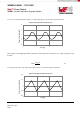
The equation (16) shows the worst case in terms of the current (I
OUT
∆I
L
2
as well as in terms of time. The inclusion of t
ON
in
the formula takes into account a new on-time triggered in case the load transient occurs at the end of the off-time. Under this
condition a new on-time is generated because the device has not yet reacted to the transient and to the consequent
deviation of V
OUT
from its steady state value (see figure below).
-0,5
0
0,5
1
1,5
2
2,5
3
-200
-150
-100
-50
0
50
100
150
200
0 10 20 30
V
OUT
I
L
t
d
I
OUT2
I
OUT1
∆I
OUT
∆V
OUT
LOAD
TRANSITION
t
ON
t
OFF
t
I
L
, V
OUT