
Data Sheet


WPMDH1152401 / 171012402
MagI
3
C Power Module
VDRM – Variable Step Down Regulator Module
we-online.com Würth Elektronik eiSos GmbH & Co. KG – Data Sheet Rev. 2.0
© December 2017
26/54
Example
The following application conditions are used as an example to show how to calculate a suitable C
OUT
value:
- V
IN
= 24V
- V
OUT
= 12V
- R
ON
= 182kΩ (f
SW
= 500kHz)
- Load transient from 0.5A to 2A and vice versa (∆I
OUT
= 1.5A)
- Max allowed undershoot or overshoot ∆V
OUT
= 120mV
C
OUT
can be calculated using the equation (15) on page 24. This equation provides two possible values depending on
whether t
d
is calculated for a positive load transient (equation (14)), generating a V
OUT
drop, or for a negative load transient
(equation (16)) resulting in a V
OUT
overshoot.
In case of positive load transient: t
d
= 4µs and C
OUT
≥ 32µF
In case of negative load transient: t
d
= 3.4µs and C
OUT
≥ 27µF
A combination of three 10µF MLCC (Würth Elektronik, part number 885012209028) and an aluminium electrolytic capacitor
(Würth Elektronik, part number 860010674014) are selected. Some margin from the calculated C
OUT
value is recommended
in order to take into account:
- Approximations within the equations to estimate t
d
and C
OUT
itself;
- Tolerances and variations of some components and parameters involved in those equations (e.g. R
ON
, t
OFF-MIN
, L, k,
etc.)
- Derating of the capacitors with DC applied voltage and temperature
The use of three MLCCs in parallel contributes to the further reduction of the total ESR.
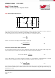
The load transients with the selected C
OUT
can be tested using the setup depicted below:
MagI³C Power
Module
Q1
C
OUT
R
Load1
R
Load2
I
OUT1
I
OUT2
V
IN
GND
VIN
VOUT
GND
24Ω
8Ω