
Data Sheet


WPMDH1152401 / 171012402
MagI
3
C Power Module
VDRM – Variable Step Down Regulator Module
we-online.com Würth Elektronik eiSos GmbH & Co. KG – Data Sheet Rev. 2.0
© December 2017
32/54
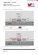
LIGHT LOAD OPERATION
Under light load conditions, the device continuously decreases the switching frequency and thereby maintains a high
efficiency.
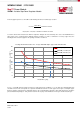
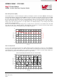
At light load, the regulator will operate in Discontinuous Conduction Mode (DCM). When the load current is above the critical
conduction point, it will operate in Continuous Conduction Mode (CCM). When operating in DCM the switching cycle begins
at an inductor current of zero ampere, increases up to a peak value, and then recedes back to zero before the end of the off-
time. Note that during the period of time when the inductor current is zero, all load current is supplied by the output
capacitor. The next on-time period starts when the voltage on the FB pin falls below the internal reference. The switching
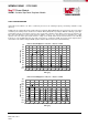
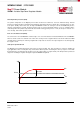
frequency is lower in DCM and varies more with load current as compared to CCM. The pictures below depict how the
current flows in the inductor during the DCM operation with two different load current (10mA and 50mA).
-0,1
0,0
0,1
0,2
0,3
0,4
0,5
0,6
0,7
0,8
0,9
1,0
0 20 40 60 80 100 120 140 160 180 200 220 240
Inductor Current [A]
Time [µs]
Inductor Current Ripple V
IN
= 24V, V
OUT
= 12V, I
OUT
= 10mA
53µs
f
SW
= 18.9kHz
-0,1
0,0
0,1
0,2
0,3
0,4
0,5
0,6
0,7
0,8
0,9
1,0
0 10 20 30 40 50 60 70 80 90 100
Inductor Current [A]
Time [µs]
Inductor Current Ripple V
IN
= 24V, V
OUT
= 12V, I
OUT
= 50mA
13µs
f
SW
= 76.9kHz