
Data Sheet


WPMDH1152401 / 171012402
MagI
3
C Power Module
VDRM – Variable Step Down Regulator Module
we-online.com Würth Elektronik eiSos GmbH & Co. KG – Data Sheet Rev. 2.0
© December 2017
36/54
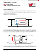
Overcurrent protection (OCP)
Current limit detection is carried out during the off-time by monitoring the current in the low-side MOSFET. Referring to the
Functional Block Diagram, when the high-side MOSFET is turned off, the inductor current flows through the load, the PGND
pin and the internal low-side MOSFET. If this current exceeds the I
CL
value, the current limit comparator disables the start of
the next on-time period. The inductor current is monitored during the off-time. As long as the inductor current exceeds I
CL
,
further on-time intervals will not occur. The next switching cycle will occur only if the FB input is less than 0.8V and the
inductor current has decreased below I
CL
(see figure below). The switching frequency is lower during current limited
operation due to the longer off-time.
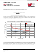
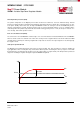
Due to the current limitation the output voltage drops (see figure below). It should also be noted that the DC current limit
varies with the duty cycle, switching frequency, and temperature. At continuous overcurrent load the module junction
temperature increase until the overtemperature protection (OTP) is triggered.
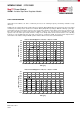
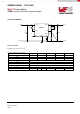
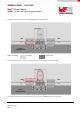
Short circuit protection
In case of short circuit, the device detects the condition during the off-time monitoring the current in the low-side MOSFET.
As long as the current remains above I
CL
, the start of the next on-time is prevented. A new on-time cycle occurs when the
current falls below I
CL
(under short condition V
OUT
= 0 and V
FB
= 0, therefore the condition V
FB
<0.8V is always fulfilled). The
device alternates very short on-time and extended off-time (see figure below).
2,0
4,0
6,0
8,0
10,0
12,0
14,0
-2,0
-1,0
0,0
1,0
2,0
3,0
4,0
0 1 2 3 4 5 6 7 8 9 10
Output Voltage [V]
Output Current [A]
Time [ms]
Current limit
Output voltage drop
2,0
2,5
3,0
3,5
4,0
4,5
5,0
0 10 20 30 40 50 60 70 80 90 100
overcurrent detected during t
OFF
I
L
< I
CL
and V
FB
<0.8V t
ON
triggered
Inductor Current [A]
Time [µs]
Inductor Current during Short Circuit V
IN
= 24V, V
OUT
= 12V, R
ON
= 182kΩ
65kHz