
Data Sheet


WPMDH1152401 / 171012402
MagI
3
C Power Module
VDRM – Variable Step Down Regulator Module
we-online.com Würth Elektronik eiSos GmbH & Co. KG – Data Sheet Rev. 2.0
© December 2017
40/54
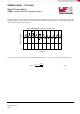
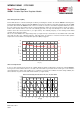
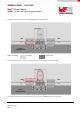
The placement of the input capacitors is highlighted in the following picture.
C
IN1
C
IN2
C
OUT1
C
OUT2
V
IN
GND
GND
V
OUT
1
2
4
3
5 6
7
VIN
RON
EN
AGND
SS
FB
VOUT
R
ON
C
SS
R
FBT
R
FBB
C
FF
PGND
MagI
3
C Module
Bottom
GROUND PLANE
R
ENT
R
ENB
PCB color coding: Top layer Bottom layer
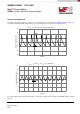
The positive terminal of C
IN1
and C
IN2
need to be very close to the VIN pin of the power module.
C
IN1
C
IN2
C
OUT1
C
OUT2
V
IN
GND
GND
V
OUT
1
2
4
3
5 6
7
VIN
RON
EN
AGND
SS
FB
VOUT
R
ON
C
SS
R
FBT
R
FBB
C
FF
PGND
MagI
3
C Module
Bottom
GROUND PLANE
R
ENT
R
ENB
The negative terminal of C
IN1
and C
IN2
needs to be very close to the PGND pad of the power module.