
Data Sheet

we-online.com
Würth Elektronik eiSos GmbH & Co. KG - Data Sheet - REV 1.0
10/25
WPMDM1500602/ 171050601
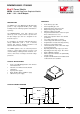
MagI³C Power Module
VDRM - Variable Step Down Regulator Module
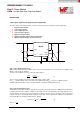
DESIGN FLOW
(As a point of reference, the worst case ripple current will occur when the module is presented with full load current
and when V
IN
= 2 * V
OUT
).
Recommended minimum input capacitance is 22µF X7R (or X5R) ceramic with a voltage rating at least 25% higher
than the maximum applied input voltage for the application. It is also recommended that attention be paid to the
voltage and temperature derating of the capacitor selected. It should be noted that ripple current rating of ceramic
capacitors may be missing from the capacitor data sheet and you may have to contact the capacitor manufacturer for
this parameter.
If the system design requires a certain minimum value of peak-to-peak input ripple voltage (ΔV
IN
) be maintained then
the following equation may be used.
(3)
If ΔV
IN
is 1% of V
IN
for a 12V input to 3.3V output application this equals 120 mV and f
SW
= 812kHz.
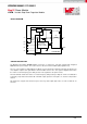
Additional bulk capacitance with higher ESR may be required to damp any resonant effects of the input capacitance
and parasitic inductance of the incoming supply lines. The MagI³C power module typical applications schematic and
evaluation board include a 150μF 50V aluminum capacitor for this function. There are many situations where this
capacitor is not necessary.
Step 3. Select Output Capacitor (C
OUT
)
None of the required C
OUT
output capacitance is contained within the module. A minimum value of 200 μF is required
based on the values of internal compensation in the error amplifier. Low ESR tantalum, organic semiconductor or
specialty polymer capacitor types are recommended for obtaining lowest ripple. The output capacitor C
OUT
may
consist of several capacitors in parallel placed in close proximity to the module. The output capacitor assembly must
also meet the worst case minimum ripple current rating of 0.5 * I
LR P-P
, as calculated in equation (4) below.
(4)
Beyond that, additional capacitance will reduce output ripple so long as the ESR is low enough to permit it. Loop
response verification is also valuable to confirm closed loop behavior. For applications with dynamic load steps; the
following equation provides a good first pass approximation of C
OUT
for load transient requirements:
(5)
For example: