
Data Sheet

we-online.com
Würth Elektronik eiSos GmbH & Co. KG - Data Sheet - REV 1.0
4/25
WPMDM1500602/ 171050601
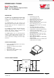
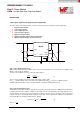
MagI³C Power Module
VDRM - Variable Step Down Regulator Module
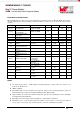
ELECTRICAL SPECIFICATIONS
MIN and MAX limits are valid for the recommended junction temperature range of -40°C to 125°C. Typical values
represent statistically the utmost probability at following conditions: V
IN
=12V, V
OUT
=3.3V, T
A
=25°C, unless otherwise
specified.
SYMBOL
PARAMETER
CONDITIONS
MIN
(3)
TYP
(4)
MAX
(3)
UNIT
V
IL-SYNC
Synchronization logic
zero amplitude
Relative to AGND
-
-
0.4
V
V
IH-SYNC
Synchronization logic
zero amplitude
Relative to AGND
1.5
-
-
V
SYNC
d.c.
Synchronization duty
cycle range
15
50
85
%
D
max
Maximum duty cycle
-
83
-
%
I
SS
Soft-start source current
V
SS
= 0V
40
50
60
µA
tss
Internal soft-start time
-
1.6
-
ms
V
FB
In-regulation feedback
voltage
V
SS
>+ 0.8V
I
OUT
= 5A
0.776
0.796
0.816
V
V
FB-OVP
Feedback over-voltage
protection threshold
-
0.86
-
V
I
FB
Feedback input bias
current
-
5
-
nA
I
Q
Non switching input
current
V
FB
= 0.86V
-
2.6
-
mA
I
SD
Shut down quiescent
current
V
EN
= 0V
-
70
-
µA
ΔV
OUT
Output voltage ripple
C
OUT
=220μF 7mΩ ESR
+ 100µF X7R
+ 2x 0.047µF
-
9
-
mVpp
ΔV
OUT
/ΔV
IN
Line regulation
V
IN
= 12V to 36V
I
OUT
=1mA
-
±0.02
-
%
ΔV
OÙT
/ΔI
OUT
Load regulation
V
IN
= 12V to 36V
I
OUT
= 1mA to 5A
-
1
-
mV/A
η
Efficiency
V
IN
=12V, V
OUT
=3.3V
I
OUT
=1A
-
86
-
%
η
Efficiency
V
IN
=12V, V
OUT
=3.3V
I
OUT
=5A
-
81.5
-
%
η
Efficiency
V
IN
=24V, V
OUT
=3.3V
I
OUT
=2A
-
80
-
%
η
Efficiency
V
IN
= 24V, V
OUT
= 3.3V
I
OUT
= 5A
-
76
-
%
NOTES
(1) The human body model is a 100pF capacitor discharged through a 1.5 kΩ resistor into each pin. Test
method is per JESD-22-114.
(2) JEDEC J-STD020
(3) Min and Max limits are 100% production tested at 25°C. Limits over the operating temperature range are
guaranteed through correlation using Statistical Quality Control (SQC) methods.
(4) Typical numbers are valid at 25°C ambient temperature and represent statistically the utmost probability
assuming the Gaussian distribution.
(5) Depending on heat sink design, number of PCB layers, copper thickness and air flow.
(6) Measured on a 3.5” x 3.5” four layer board, with 104µm (3 ounce) copper on outer layers and 70µm (2
ounce) copper on inner layers, sixty 10 mil thermal vias, no air flow, and 1W power dissipation