
Data Sheet

WLMDU9456001JT / 172946001
MagI
3
C Power Module
LDHM - LED Step Down High Current Module
We-online.com Würth Elektronik eiSos GmbH & Co. KG – Data Sheet Rev. 1.0
© May 2016 14/35
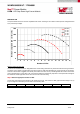
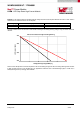
DESIGN FLOW
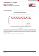
The picture below shows the minimum adjustable LED current according to the number of LEDs (forward voltage assumed
3,2V) and the input voltage.
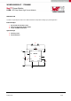
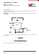
Maximum Switch Current Limit
The LED Driver Module features an integrated switch current limiting mechanism to prevent the LEDs from being overdriven.
The switch current limiter is triggered when the switch current is three times exceeding the current level set by the resistor.
Once the current limiter is triggered, the internal power switch turns OFF for 3.6 μs to demagnetize the inductor until inductor
current reduces back to normal level. The current limiting feature is exceptionally important to avoid permanent damage of
the LED driver module application circuit due to short circuit of the LED string.
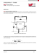
Step 2 Select the appropriate number of LEDs
The on-time of the internal switch should not be shorter than 400 ns. The number of LEDs (typical forward voltage at 3.2 V)
to input voltage is constrained by that as shown in the following table.
No. of LED
1
2
3
4
5
6
-
16
Max. V
IN
(V) 12 20 30 40 50 60
0
50
100
150
200
250
1 2 3 4 5 6 7 8 9 10 11 12 13 14 15 16
Minimum adjustable LED current [mA]
Number of LEDs
Vin = 12V
Vin = 24V
Vin = 36V
Vin = 48V
Vin = 60V