
Data Sheet

WLMDU9456001JT / 172946001
MagI
3
C Power Module
LDHM - LED Step Down High Current Module
We-online.com Würth Elektronik eiSos GmbH & Co. KG – Data Sheet Rev. 1.0
© May 2016 15/35
DESIGN FLOW
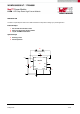
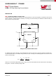
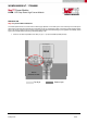
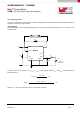
Step 3 Layout and EMI considerations
The overall performance of the LED driver module highly depends on the PCB layout. Poor board layout can disrupt the
performance of the LED driver module and surrounding circuitry by contributing to EMI, ground bounce and resistive voltage
drop in the traces. These can send incorrect signals to the LED driver module resulting in poor regulation and stability. Good
layout can be implemented by following a few simple design rules.
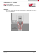
∂ Place C
IN
as close as possible to the LED+ pin (pin 1 + pin 2) and PGND exposed pad (EP).
C
IN1
C
IN2
C
OUT2
C
OUT1
Exposed pad
1
2
234567
RIADJ
VIN
GND
LED+ LED-DIM AGND ISET IFIX
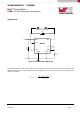
Bottom
GROUND PLANE
PGND
Top layer
Bottom layer