
Data Sheet


WLMDU9456001JT / 172946001
MagI
3
C Power Module
LDHM - LED Step Down High Current Module
We-online.com Würth Elektronik eiSos GmbH & Co. KG – Data Sheet Rev. 1.0
© May 2016 2/35
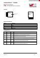
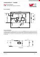
PACKAGE
LED+
LED+
DIM
AGND
ISET
IFIX
LED-
1
2
3
4
5
6
7
6
7
Exposed Pad = PGND
Connect to AGND
EP
Top view
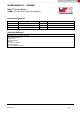
MARKING DESCRIPTION
Marking
Description
WE Würth Elektronik trade name
Y Year
M Month
LLLL Lot trace code
G3 Lead finish code per JEDEC norm (green 3 mat sin)
WE201 Part identifier
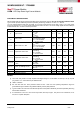
PIN DESCRIPTION
SYMBOL PIN # TYPE PIN DESCRIPTION
LED+ 1, 2 Power
Supply input and rail connection to the anode of the LED string.
DIM 3 Input
Dimming control signal input. Left floating enables the driver. Optional: apply a logic
level PWM signal to control the brightness of the LED string.
AGND 4 Supply
The analog ground pin is the reference point for all stated voltages and must be
connected to the exposed pad (EP) externally.
ISET 5 Input
Connect a resistor between this pin and GND to adjust the LED current up to
450mA. If the default LED current of 350mA is desired, leave this pin floating.
IFIX 6 Input
Connect this pin to GND to set the default LED current of 350mA. In case a different
value of LED current is required, leave this pin floating.
LED- 7 Power The current return pin of the LED string. Connect to the cathode of the LED string.
PGND EP Power
Exposed Pad. Connect to copper plane(s) with thermal vias for thermal
performance. Must be electrically connected to pin 4.
6
7
Package marking
YMLLLLG3
WE201