
Data Sheet
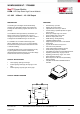


WLMDU9456001JT / 172946001
MagI
3
C Power Module
LDHM - LED Step Down High Current Module
We-online.com Würth Elektronik eiSos GmbH & Co. KG – Data Sheet Rev. 1.0
© May 2016 5/35
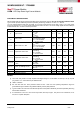
ELECTRICAL SPECIFICATIONS
MIN and MAX limits are valid for the recommended junction temperature range of -40°C to 125°C unless otherwise stated.
Typical values represent statistically the utmost probability at following conditions: V
IN
=48V, I
LED
= 350 mA.
V
IN
is the voltage applied across LED+ and GND. I
IN
is the input current flowing into the LED+ node. I
LED
is a LED current
flowing into the LED- pin. V
LED
is the voltage applied across LED+ and LED-. V
DIM
is the voltage applied across the DIM pin
to GND. Resistor R
IADJ
connect from ISET pin to GND.
SYMBOL
PARAMETER
TEST CONDITIONS MIN
(3)
TYP
(4)
MAX
(3)
UNIT
I
IN
Input current
V
IN
= 4.5 to 60V
V
LED
= 0V;
V
DIM
=0V
T
J
= 25°C
2.1 2.65 3.0 mA
I
LED
LED current
V
LED
= 24V;
IFIX connected to GND;
R
IADJ
= not connected;
T
J
= -40°C to 125°C
337 350 371 mA
I
LED-60V
LED current V
IN
= 60V
V
IN
= 60V;
V
LED
= 36V;
IFIX connected to GND;
R
IADJ
= not connected;
T
J
= -40°C to 125°C
338 350 374 mA
I
LED-ADJ450
Adjustment LED current
V
LED
= 24V;
IFIX floating;
R
IADJ
= 2.33kΩ;
T
J
= -40°C to 125°C
437 450 483 mA
I
LED-ADJ300
Adjustment LED current
V
LED
= 24V;
IFIX floating;
R
IADJ
= 3.5 kΩ;
T
J
= -40°C to 125°C
282 300 316 mA
I
LED-SHORT
LED short circuit current V
IN
= 60V
V
LED
= 0V;
V
IN
= 60V;
DIM = open
800 920 1020 mA
I
LED-LEAK
“LED-“ pin leakage current
V
LED
= 0V;
V
IN
= operating max;
DIM = 0V
1.2 µA
V
DIM
DIM pin threshold
V
DIM
increasing 1.0 1.3 V
V
DIM-HYS
DIM pin hysteresis
0.25 V
f
SW
Switching frequency
0.72 0.8 0.92 MHz
NOTES
(1) The human body model is a 100pF capacitor discharged through a 1.5 kΩ resistor into each pin. The pin 6 ( IFIX
pin) passes ± 1 kV. Test method is per JESD22-AI14S.
(2) JEDEC J-STD020
(3) Min and Max limits are 100% production tested at 25°C. Limits over the operating temperature range are
guaranteed through correlation using Statistical Quality Control (SQC) methods.
(4) Typical numbers are valid at 25°C ambient temperature and represent statistically the utmost probability assuming
the Gaussian distribution.
(5) θ
JA
measured on a 43.3 mm x 76.2 mm four layer board, with 35 µm copper , thirty five 0.3 mm thermal vias, no air
flow, and 1 W power dissipation.