
Datasheet


we-online.com
Würth Elektronik eiSos GmbH & Co. KG - Data Sheet - REV 1.0
9/25
WPMDM1500602/ 171050601
MagI³C Power Module
VDRM - Variable Step Down Regulator Module
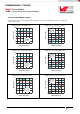
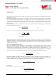
DESIGN FLOW
4 Steps (plus 3 Optional) to design the power application
The next 7 simple steps will show how to select the external components to design your power application:
1. Program output voltage
2. Select input capacitor
3. Select output capacitor
4. Select soft-start capacitor
5. Optional: Voltage tracking
6. Optional: Program under voltage lockout divider
7. Optional: Synchronization to an external clock
C
IN
SYNC
VIN
EN PGND SS/TRK
FB
VOUT
Module
R
FBT
R
FBB
C
SS
C
OUT
AGND
1
2
3
EP
6
4
5
7
R
ENT
R
ENB
1.
7.
2. 3.
4.
5.
6.
V
IN
V
OUT
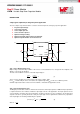
Step 1. Select Output Voltage (V
OUT
)
Output voltage is determined by a divider of two resistors connected between V
OUT
and ground. The midpoint of the
divider is connected to the FB input.
The ratio of the feedback resistors for a desired output voltage is:
(1)
These resistors should be chosen from values in the range of 1kΩ to 10kΩ.
For V
OUT
= 0.8V the FB pin can be connected to the output directly and R
FBB
can be set to 8.06kΩ to provide
minimum output load. A table of values for R
FBT
and R
FBB
, is included in the applications circuit.
Step 2. Select Input Capacitor (C
IN
)
The MagI³C power module contains a small amount of internal ceramic input capacitors. Additional input capacitance
is required external to the module to handle the input ripple current of the application. The input capacitor can be
several capacitors in parallel. This input capacitance should be located in very close proximity to the module. Input
capacitor selection is generally directed to satisfy the input ripple current requirements rather than by capacitance
value. Input ripple current rating is dictated by the equation:
(2)
where