
Datasheet


WPMIx9200501S / 1779205x1
MagI
3
C Power Module
FISM – Fixed Isolated SIP Module
we-online.com Würth Elektronik eiSos GmbH & Co. KG – Data Sheet Rev. 1.0
©July 2016 7/22
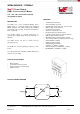
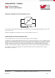
INTENDED USE – Typical Application
AC
Conductor
track
1
2
4
3
+VIN
-VIN
+VOUT
-VOUT
DC
DC
Load
L
N
AC
“Reinforced Isolation“
Power Supply Unit (PSU)
Power Module (isolated)
Primary Circuit Secondary Circuit (SELV Circuit)
+VOUT
-VOUT
DC
“Functional Isolation“
+
-
DC Bus
SELV
Conductor
track
The 1779205x1 MagI
3
C Power Modules are only intended to be used as a CLASS III equipment according to the UL60950-1
standard. That requires that the Power Module is supplied by a SELV (safe extra low voltage) circuit which provides
protection against electric shock. There are no HAZARDOUS voltages present in CLASS III Equipment.
A SELV circuit is a secondary circuit that is designed to be protected from excessive voltages (≥42 Vac or ≥ 60Vdc) during
normal operating conditions and single fault conditions. A reinforced isolation is required at the boundary between the
primary and the secondary circuit.
A circuit which has no direct connection to the primary circuit and derives its power from a transformer, converter or
equivalently isolated device, or a battery, is defined as a secondary circuit.
In accordance to the Safety Standard UL60950-1, functional isolation (insulation) is defined as:
“1.2.9.1 Functional Insulation: insulation that is necessary only for the correct functioning of the equipment
NOTE: Functional Insulation by definition does not protect against electric shock. It may, however, reduce the likelihood of
ignition and fire.”
“1.2.9.5 Reinforced Insulation: single insulation system that provides a degree of protection against electric shock equivalent
to Double Insulation under the conditions specified in this standard.
NOTE: The Term “insulation system” does not imply that the insulation has to be in one homogeneous piece. It may
comprise several layers that cannot be tested that cannot be tested as Basic Insulation and Supplementary Insulation
The above Figure shows a typical application of an isolated Power Module. V
DC1
is a hazardous voltage and
V
DC2
is a SELV voltage.
ISOLATION VOLTAGE
To verify the integrity of an isolation a test voltage is applied for a specified time across a component that is designed to
provide electrical isolation. This test is known as a ‘Hi Pot Test’, ‘Flash Tested’, ‘Withstand Voltage’, ‘Proof Voltage’,
‘Dielectric Withstand Voltage’ & ‘Isolation Test Voltage’.
All isolated Power Modules are all 100% production tested at their stated isolation voltage. This is 1kVDC for 1 second.
The isolation test voltage indicated in this datasheet is for voltage transient immunity only. It does not allow this part to be
used within a safety isolation system.
The part will function properly with several hundreds of volts applied continuously across the isolation barrier, however
surrounding components must be individually analyzed to ensure proper insulation. Isolation measures are taken to prevent
any user-accessible circuitry from causing harm.