
User manual

Compile and run the examples on XMC™ microcontroller
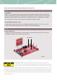
1 Compile the project by clicking icon
2 Click icon
to open "Debug Configuration" dialog
Step 3 – 4 must be done only when starting a new project.
3 To create a new debug configuration click on
4 Start debug session by clicking "Debug"
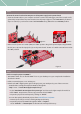
Make sure at this point that the "power on" switch in the power board - SW4 - is in the "ON" position.
The debugger starts code download and switches from "DAVE CE" perspective to the
"Debug" perspective.
5 Click "Resume" to restart the code execution
6 The buck converter is now running
STEP 5
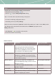
Product summary
Type Description Ordering code (OPN)
XMC4200-F64X256 80 MHz ARM® Cortex®-M4F with DSP instructions
and Floating Point Unit (FPU), 256 kB flash,
40 kB RAM, 1kB cash, rich analog mixed signal,
advanced timer/HRPWM unit and communica-
tion peripherals in PG-LQFP-64 package
XMC4200F64K256ABXQSA1
XMC1302-T038X0200
32 MHz ARM® Cortex®-M0 with MATH co-processor,
200 kB flash, 16 kB RAM, rich analog mixed sig-
nal, timer/PWM and communication peripherals
in PG-TSSOP-38 package
XMC1302T038X0200AAXUMA1
XMC4200-Q48X256 XMC4200 with 256 kB flash, 40 kB RAM, 1 kB
cash in PG-VQFN-48 package, used as on-board
debugger controller
XMC4200Q48K256ABXUMA1
BSC0924NDI Dual N-channel (high-side and low-side)
OptiMOS™ MOSFET
BSC0924NDI
IRS2011SPBF High-side and low-side MOSFETs gate driver IC IRS2011SPBF
IFX1763XEJ V33 Wide range input voltage, low dropout voltage
regulator supplying up to 500mA
IFX1763XEJV33XUMA1