
Installation Sheet

WAC Lighting
www.waclighting.com
Phone (800) 526.2588 • Fax (800) 526.2585
Headquarters/Eastern Distribution Center
44 Harbor Park Drive • Port Washington, NY 11050
Phone (516) 515.5000 • Fax (516) 515.5050
Western Distribution Center
1750 Archibald Ave • Ontario, CA 91761
Phone (800) 526.2588 • Fax (800) 526.2585
WAC Lighting retains the right to modify the design of our products at any time as part of the company's continuous improvement program. DECEMBER, 2014
INSTALLATION INSTRUCTION
FLIP - dweLED™
BL-1021R, BL-1021L
PREPARATION
- Carefully unpack your new xture and lay out all the parts on
clear area. Be careful not to lose any small parts necessary for
installation.
- Remove the mounting plate (K1) from xture
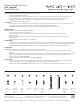
PORTABLE INSTALLATION (Fig. 1)
1. Drill holes in the wall aligned with the key-hole location in
mounting plate (K1).
2. Insert plastic anchors (F1) into holes. Insert wood screws (E1) into
anchors leaving enough length to hang mounting plate (K1).
3. Hang mounting plate (K1) and tighten screws until mounting
plate is secured to the wall.
4. Place the xture onto the mounting plate and secure it with
the allen screws (J1) using the allen wrench (C1) provided.
5. Install optional cord cover if desired. Drill holes in the wall aligned
with the hole locations on the cord bracket (G1). Insert plastic
anchors (F1) into wall. Secure bracket to the wall with wood
screws (E1).
6. Place the cord into the bracket (G1). Snap the cord cover (H1)
over the bracket and plug into outlet.
7. This lamp features a dimmer switch. Press and release to turn on/
o. When xture is on, press and hold the switch to cycle from
dim to bright and release when desired brightness is reached.
IMPORTANT SAFETY INSTRUCTIONS
This portable lamp has a polarized plug (one blade is wider than the
other) as a safety feature to reduce the risk of electric shock. This
plug will t a polarized outlet only one way. If the plug does not t
fully in the outlet, reverse the plug. If it still does not t, contact a
qualied electrician. Never use with an extension cord unless the
plug can be fully inserted. Do not change or alter the plug.
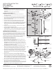
FIXTURE INSTALLATION (FIG.3)
1. Shut o power at the circuit breaker. If necessary, remove old
xture, including mounting hardware.
2. Cut power cord to 7” length (from center of backplate). Pull cord
through from grommet hole in order to connect to main power.
(CAUTION: Fixture cannot revert to plug-in version once the cord
and plug are cut o) Remove grommet from lamp base and insert
hole plug (D1) provided to cover hole.
3. Unscrew the allen screw (J1) using allen wrench (C1) provided.
Remove the back plate (K1) from lamp base. Unscrew two screws
(L1) and remove metal plate (N1) from lamp base. Then replace
two screws (L1) over power cord and bare copper as strain relief.
4. Attach the mounting plate (K1) onto the junction box using two
junction box screws (B1). Make sure the mounting plate (K1) in
horizontal position. The side of mounting plate (K1) marked “GND”
must face out.
5. Connect the electrical wires as shown in Fig. 2, making sure
that all wire connectors (A1) are secured. If your outlet box has a
ground wire (green or bare copper), connect the xture’s ground
wire to it. Otherwise, connect the xture’s ground wire directly to
the mounting plate (K1) using the green screw (I1) provided. After
wires are connected, tuck them carefully inside the junction box.
6. Place the xture over the mounting plate (K1) and secure it using
allen screws (J1) by allen wrench (C1) provided.
7. This lamp features a touch switch. Press and release to turn on/o.
When xture is on, press and hold the switch to cycle from dim to
bright and release when desired brightness is reached.
F1
K1
C1
J1
E1
F1
E1
G1
H1
Drill two holes
on wall
Plastic Anchor
Wood Screw
Cord Bracket
Cord Cover
Dimmer switch
Key hole
Allen wrench
Fixture
Fixture Wires
Black or
Smooth
Fixture Wires
White or
Ribbed
Fixture Wires
Bare wire
(Ground)
House Wires
Black
(Hot)
House Wires
White
(Neutral)
House Wires
Green or Bare Copper
(Ground)
Fig.2 Wiring
I1
C1
J1
B1
A1
K1
L1
N1
D1
Hole plug
Metal plate
Screw
Dimmer switch
Lamp base
Allen wrench
Green screw
Mounting plate
Wire
connector
Fig.3