
Installation Sheet


WAC Lighting
www.waclighting.com
Phone (800) 526.2588 • Fax (800) 526.2585
Headquarters/Eastern Distribution Center
44 Harbor Park Drive • Port Washington, NY 11050
Phone (516) 515.5000 • Fax (516) 515.5050
Western Distribution Center
1750 Archibald Ave • Ontario, CA 91761
Phone (800) 526.2588 • Fax (800) 526.2585
WAC Lighting retains the right to modify the design of our products at any time as part of the company's continuous improvement program. AUGUST, 2014
INSTALLATION INSTRUCTION
Stretch - dwelLED™
BL-1630
IMPORTANT SAFETY INSTRUCTIONS
This portable lamp has a polarized plug (one blade is wider than the
other) as a safety feature to reduce the risk of electric shock. This
plug will t a polarized outlet only one way. If the plug does not t
fully in the outlet, reverse the plug. If it still does not t, contact a
qualied electrician. Never use with an extension cord unless the
plug can be fully inserted. Do not change or alter the plug.
PERMANENT INSTALLATION
1. Shut o power at circuit breaker. If necessary, remove old xture,
including mounting hardware.
2. Unscrew the screw (M1) and take out the metal plate (I1) from
inside the xture back plate.
3. Cut power cord to 7” length (from center of the xture back
plate). Pull cord through grommet hole in order to connect to main
power. (CAUTION: FIXTURE CANNOT REVERT TO PLUG-IN VERSION
ONCE THE CORD AND PLUG ARE CUT OFF.)
Remove grommet from base and insert hole plug (N1) provided to
cover hole
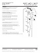
FOR SWITCH BOX MOUNTING (Fig. 2)
1. Secure mounting plate (B1) to the switch box (P1) using screws
(K1). The side of the mounting plate marked “GND” (B1)
must face out.
FOR JUNCTION BOX MOUNTING (optional Fig. 3)
2. Secure the mounting ring (Y1) to the junction box (F1) using
junction box screws (K1). Make sure the two holes (spacing 2-3/4”)
are vertically aligned as shown in Fig, 3.
3. Put the mounting plate (B1) and the conversion plate (Q1) onto
the mounting ring (K1). Make sure the two holes on the mounting
plate (B1) are aligned with the two slots on the conversion plate
(Q1) and the two holes on the mounting ring (Y1).
Fasten them using the long screws (Z1).
CONNECTING THE WIRES (Fig. 4)
4. Connect the electrical wires as shown in Fig, 3, making sure that
all wire connectors (J1) are secured. If your outlet box has a green
or bare copper ground wire, connect the xture’s ground wire to it.
Otherwise, connect the xture’s ground wire directly to the
mounting plate (B1) using the green screw provided. After wires are
connected, tuck them carefully inside the junction box.
5. Place the xture back plate (E1) over the mounting
plate (B1) and secure with screws (D1).
FIG.4
Fixture Wires
Black or
Smooth
Fixture Wires
White or
Ribbed
Fixture Wires
Bare Copper
(Ground)
House Wires
Black
(Hot)
House Wires
White
(Neutral)
House Wires
Green or Bare Copper
(Ground)
FIG.2
For Switch Box
P1
J1
B1
K1
D1
I1
M1
E1
N1
FIG.3
For Junction Box
F1
Y1
K1
Q1
B1
Z1
switch
box
wire
connector
mounting
plate
Box
screw
screws
base
screw
Junction
box
Mounting
plate
Mounting
screw
Conversion
plate
Mounting
plate
Long
screw
xture
metal
plate
screw