
Installation Sheet

WAC Lighting retains the right to modify the design of our products at any time as part of the company's continuous improvement program. 2
waclighting.com
Phone (800) 526.2588
Fax (800) 526.2585
Headquarters/Eastern Distribution Center
44 Harbor Park Drive
Port Washington, NY 11050
Central Distribution Center
1600 Distribution Ct
Lithia Springs, GA 30122
Western Distribution Center
1750 Archibald Avenue
Ontario, CA 91760
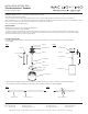
INSTALLATION INSTRUCTION
Tube Architectural - Pendant
DS-PD05, DS-PD06, DS-PD08
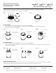
3. Align the top of the cast ball with the top of the cut pendant stem and temporarily lock it in place by tightening one of the screws into
the side of the stem. Use the provided drill bit to drill a hole through the stem wall using the unthreaded hole.
4. Loosen the screw. Rotate the cast ball 180° and retighten the screw. Drill another hole using the unthreaded hole on the other side
of the stem wall.
5. Loosen the screw. Rotate the cast ball 90° and fully lock both screws through the two tap holes to secure the cast ball.
(Refer to Fig. 5 and 6)
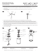
6. Align the pendant assembly- Refer to Fig. 7. Tighten bottom nut securely. Guide xture wire up through assembly.
Note: for longer supsensions lengths, it may be necessary to replace the existing xture wire with longer feedwire provided in xture
package. Rotate plate clockwise, and secure it to xture body using screws and gasket. Secure wire feed with clamp above cast ball.
7. Pull power supply wires out of junction box. Connect black xture wire to hot wire, white xture wire to neutral wire and green xture wire
to ground. For 0-10V dimming, connect purple xture wire to hot dimming wire and gray xture wire to neutral dimming wire. If not
utilizing dimming, terminate the dimming wires by capping them separately. After wires are connected securely, tuck them carefully inside
the junction box. Refer to Fig.8
8. Secure mounting plate to junction box using junction box screws. Raise the canopy to the mounting plate and rotate clockwise until secure
to the ceiling. Refer to Fig.9
Screw Drill hole
Screw
Cast ball
Drill
Screw hole
Screw hole
Feed wire
clamp
Junction box
(by others)
Rotate canopy
until secure to
the ceiling
Wire connect
Mounting plate
Canopy
Mounting
Plate
Stem
Canopy
Washer
Fixture
Plate
Nut
Fig.5
Fig.7
Fig. 6
Fig. 8 Fig. 9
CloseOpen