
Installation Guide

WAC Lighting
www.waclighting.com
Phone (800) 526.2588 • Fax (800) 526.2585
Headquarters/Eastern Distribution Center
44 Harbor Park Drive • Port Washington, NY 11050
Phone (516) 515.5000 • Fax (516) 515.5050
Western Distribution Center
1750 Archibald Ave • Ontario, CA 91761
Phone (800) 526.2588 • Fax (800) 526.2585
WAC Lighting retains the right to modify the design of our products at any time as part of the company's continuous improvement program. JULY, 2014
INSTALLATION INSTRUCTION
60W, 75W Enclosed Electronic Transformers
EN-1260-RB-AR, EN-1275-RB-AR
CAUTION – TO REDUCE RISK OF FIRE AND ELECTRICAL SHOCK
• Always turn o power at main switch prior to installation.
• Intended for installation by a qualied electrician.
• System is intended for installation in accordance with National Electric Code, and local regulations. Consult with local inspec-
tor to assure compliance.
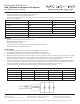
EN-1260-RB-AR EN-1275-RB-AR
MAX LOAD 60W 75W
MIN LOAD 20W 20W
INPUT VOLTAGE 120V 120V
INPUT CURRENT 0.53A 0.63A
OUTPUT VOLTAGE 11.6V 11.6V
MAX CASE TEMP 90º C (194ºF)
AMBIENT TEMP -20º C ~ +50º C (-4ºF ~ 122ºF)
FEATURES
• Electronic short circuit protection with auto reset.
• Overload protection with auto reset.
• Automatic thermal regulation.
• Soft start delay to preserve bulb life, for use with tungsten lament lamps.
• Dimmable with electronic dimmer switches.
INSTALLATION:
1. For the EN-1260-R-AR model, use a minimum of #18 AWG for the output wire.
2. For the EN-1275-R-AR model, use a minimum of #16 AWG for the output wire.
3. Transformers must be installed away from heat sources and accessible for service.
4. Note: Enclosed transformer is UL listed. The transformer box has a separate line volt, and low volt wiring compartments. Trade
size knock out are provided on both compartments. Connect building wires to like color transformer wires with wire nuts.
Building ground wire may be green or un-insulated, and attaches to green wire from transformer box.
5. Connect out put wires from transformer to xture wires with wire nuts. Where multiple xtures are involved several xtures
wires can be joined by use of the same wire nut. Wires to xtures may be chain wired or “ home run” wired back to the trans-
former. High frequency output is only readable with a true RMS meter, with sucient range capability.
6. Low volt wiring concealed in walls and ceilings requires enclosed and clamped connections.
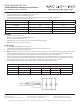
MAXIMUM LENGTH / VOLTAGE DROP GUIDELINE
WIRE SIZE 35 W 50 W 60 W 75W
18 GAUGE 10 FT 9 FT 8 FT 7FT
16 GAUGE 14 FT 13 FT 11 FT 10FT
14 GAUGE 21 FT 19 FT 15 FT 14FT
12 GAUGE 28 FT 25 FT 21 FT 20FT