
Installation Sheet

dweLED.com
Phone (800) 526.2588
Fax (800) 526.2585
Headquarters/Eastern Distribution Center
44 Harbor Park Drive
Port Washington, NY 11050
Central Distribution Center
1600 Distribution Ct
Lithia Springs, GA 30122
Western Distribution Center
1750 Archibald Avenue
Ontario, CA 91760
2
INSTALLATION INSTRUCTION
PD-16063
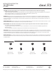
Fixture Wires
Black or
Smooth
Fixture Wires
White or
Ribbed
Fixture Wires
Bare wire
(Ground)
House Wires
Black
(Hot)
House Wires
White
(Neutral)
House Wires
Green or Bare Copper
(Ground)
1. Shut o the power at the circuit breaker and remove existing xture, including the crossbar.
2. Carefully unpack your new xture and lay out all the parts on a clear area. Be careful not to lose any small parts necessary for installation.
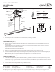
3. Remove the mounting screw (B) from the xture.
4. Adjust the xture wire length by pushing the cable gripper on the canopy and pulling the wire as desired. Make sure the wires are
the same length.
a. Retract these wires close to a desirable length to within the canopy before securing the xture in place. Using the cable gripper to
adjust more than 18” of wire length is not desirable.
b. Warning: Shortening these cables without professional helps or electronic background is not advisable. Any modications to the
xture will result in voiding the warranty of the product.
5. Drill holes in the wall aligned with the key holes located on the mounting back plate. Insert the plastic anchor (D).
6. Secure the mounting back plate to the junction box using the screws provided with the junction box. Fasten the mounting back plate
to the wall with the plastic anchors using the wood screws (C) provided.
(i)using any other non-original-manufacturer provided junction box screw may result in safty issue.
(ii) The side of the mounting plate marked “GND” must face out.
7. Connect the driver’s input wires to junction box wires as shown (Fig. 2). Make sure that all wire connectors (A) are secure. If your outlet
box has a green or bare copper ground wire, connect the driver’s ground wire to it. Otherwise, connect the xture’s ground wire directly
to the back plate using the green screw provided. After wires are connected, tuck them carefully inside the junction box.
8. Secure the xture to the mounting back plate using the mounting screw (B).
7 1/4"
4"
G
N
D
1 3/8" 1 3/4"
14 1/8"
Mounting Screw
Mounting back plat
Canopy
Suspending line
(MAX 120")
Fixture
Push up
Cable gripper
Driver
Wood Screw
Plastic Anchor
Junction box
Wire Connector
A
Junction Box Screw
Instruction:Adjust
the xture wire
length by pushing
the cable gripper on
the canopy and
pulling the wire as
desired.
B
D
C