
Installation Sheet

2
waclighting.com
Phone (800) 526.2588
Fax (800) 526.2585
Headquarters/Eastern Distribution Center
44 Harbor Park Drive
Port Washington, NY 11050
Central Distribution Center
1600 Distribution Ct
Lithia Springs, GA 30122
Western Distribution Center
1750 Archibald Avenue
Ontario, CA 91760
PREPARATION
1. Shut o the power at the circuit breaker and remove
existing xture, including the crossbar.
2. Carefully unpack your new xture and lay out all the
parts on a clear area. Be careful not to lose any small
parts necessary for installation.
MOUNTING THE FIXTURE Fig. 1
3. Remove the mounting screw (D1) from the xture.
4. Choose suitable stems for desired length and connect.
5. Thread wire through stems and canopy. Tighten the canopy,
stems, and xture body.
CONNECTING THE WIRES Fig. 2
6. Cut the extra wire thread from the xture.
7. Connect the driver input wire with junction box as shown in
Fig.2, make sure that all wire connectors (A1) are secured.
If your outlet box has a green or bare copper ground wire,
connect the xture’s ground wire to it. Otherwise, connect
the xture’s ground wire directly to the mounting plate
using the green screw provided. After wires are connected,
tuck them carefully inside the junction box.
*Requires Driver to be recessed within the junction box.
COMPLETING THE INSTALLATION (Fig. 1, 2, 3)
8. Secure mounting plate to the junction box using junction
box screws (C1). The side of the mounting plate marked
“GND” must face out.
9. Connect the driver output wire with xture wire as shown in
Fig. 2 making sure that all wire connectors (B1) are secured.
10. Place the xture over the mounting plate and secure with
mounting screws (D1).
11. Rotate the glass onto the lamp housing.
12. For slope ceiling application, rotate wire at the top of the
stem to ensure luminaries is aiming down (Fig. 3).
Fixture Wires
Black or
Smooth
Fixture Wires
White or
Ribbed
Fixture Wires
Bare wire
(Ground)
House Wires
Black
(Hot)
House Wires
White
(Neutral)
House Wires
Green or Bare Copper
(Ground)
Fig. 2 Wiring Fig. 3
Turn to down
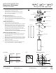
Fig.1
Back Plate Dimensions
A1
B1
C1
D1
Wire Connector
Wire Connector
Mounting Plate
Canopy
Mounting Screw
Swivel
Junction Box
Driver
Ground Wire
Ground Wire Screw
Rod
Lamp Housing
3 x 12” rods
1 x 6” rod
Junction Box Screw
Glass
1 3/4”
1 1/2”
Ø4 3/4”
INSTALLATION INSTRUCTION
Elementum - LED Pendant
PD-26611/PD-26616