
Installation & Assembly

WAC Lighting
www.waclighting.com
Phone (800) 526.2588 • Fax (800) 526.2585
Headquarters/Eastern Distribution Center
44 Harbor Park Drive • Port Washington, NY 11050
Phone (516) 515.5000 • Fax (516) 515.5050
Western Distribution Center
1750 Archibald Ave • Ontario, CA 91761
Phone (800) 526.2588 • Fax (800) 526.2585
WAC Lighting retains the right to modify the design of our products at any time as part of the company's continuous improvement program. JUNE, 2014
INSTALLATION INSTRUCTION
Flexrail1™ - Power Feed Cable
HM1-PCC
SAFETY INSTRUCTIONS:
Only a qualied electrician must install system. System is intended for installation in accordance
with National Electric Code, local and Federal code specications.
To reduce the risk of re, electrical shock and injuries to persons:
1. Read all instructions.
2. Turn o power at main switch before installing or modifying the system.
3. Do not install within six inches of any curtain or combustible materials.
4. Do not install less than 5 feet above a oor.
5. Do not install in damp or wet locations.
6. Do not install concealed, or extended through building walls.
7. Do not attempt to energize anything other than a track light xture.
8. Do not load rail to more than 20 amps per circuit.
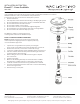
The HM1-PCC: Installs to a ceiling junction box.
Consult general instructions for installation steps.
FIELD CUTTING THE FLEXIBLE POWER FEED:
NOTE: The exible power feed is used for slopped ceiling and
custom suspension length applications. It supplies power only,
it is not intended to support rail.
1. Separate the canopy from the base plate by loosening the
three canopy screws. Remove base plate and undo wire connections.
2. Remove the collar-nut, to release the cord from the canopy.
3. Loosen the cord tter from the strain relief tting, but do not remove it.
4. Slide the cord tter and it’s internal parts down the length of the wire
and just below the desired cut spot.
5. Before cutting be sure to leave sucient wire length to complete
wire connections.
6. Trim the outer jacket.
7. Make sure the bushing and clamp are seated inside the cord tter.
Re-tighten the cord tter and give it a sharp tug to check the grip.
8. Insert the cord tter back into the canopy and install the collar-nut.
9. Strip 3/8” of insulation from the wire ends and re-connect with building
wires in the original order.
10. Reinstall canopy to base plate.