
Installation & Assembly


WAC Lighting
www.waclighting.com
Phone (800) 526.2588 • Fax (800) 526.2585
Headquarters/Eastern Distribution Center
44 Harbor Park Drive • Port Washington, NY 11050
Phone (516) 515.5000 • Fax (516) 515.5050
Western Distribution Center
1750 Archibald Ave • Ontario, CA 91761
Phone (800) 526.2588 • Fax (800) 526.2585
WAC Lighting retains the right to modify the design of our products at any time as part of the company's continuous improvement program. SEPTEMBER, 2015
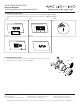
a. With HANGER b. With 1/2
CHANNEL (not included)
c. With 3/4
CHANNEL (not included)
d. With 1 1/2
CHANNEL (not included)
e. With ROUND
CHANNEL (not included)
INSTALLATION INSTRUCTION
Precision Multiples
4” LED Adjustable recessed downlights MT-4LD
Fig. 1 Fig. 2 Fig. 3 Fig. 4 Fig. 5
2. Install the mounting frame using two hanger bars. Bars are notched on
the ends to t over “T” bars in suspended ceilings.Hanger bars include
a captive mounting “screw-nail” for ease of installation (Fig.6). Align the
bottom of the hanger bar with the bottom of the wood joist. Secure the
“screw-nail” on each end by screwdriver (Fig. A), or by hammer (Fig. B).
3. Pinch the adjustable bracket, slide the xture along hanger bars into
desired location (Fig. C).
4. The junction box is suitable for branch wiring and has trade size knock-
outs and integral non-metallic sheathed cable connectors.
Fig. C
Fig. 6
Fig. A Fig. B Fig. C
Fig. A / Fig. B
IMPORTANT SAFETY INSTRUCTIONS
1. Read all instructions before installing.
2. System is intended for installation by a qualied electrician in accordance with the National Electrical Code and
local regulations.
3. Go to the main fuse box, or circuit breaker. Place the main power switch in the “OFF” position and unscrew the fuse(s) or switch ”OFF” the
circuit breaker switch(es) that control the power to the xture or room that you are working on.
4. Place the wall switch in the “OFF” position.
INSTRUCTIONS DE SÉCURITÉ IMPORTANTES
1. Lisez toutes les instructions avant d’installer.
2. Système est destiné à être installé par un électricien qualié en conformité avec le code national de l’électricité et
les règlements locaux.
3. Accédez au panneau central de disjoncteurs ou de fusibles de votre demeure et placez l’interrupteur principal en position d’arrêt («OFF »).
4. Placez l’interrupteur mural en position d’arrêt (« OFF »).
OVERVIEW:
Housing is new construction
and requires a trim or invisible trim.
MOUNTING:
1. Adjust the housing to proper height by loosening the wing nut on both adjustable brackets and set the basic plate so that the bottom edge
of the frame is ush to the nished ceiling (Fig.1, Fig.2, Fig.3, Fig.4 and Fig.5) . Tighten the wing nut.
Table 1 - HOUSING OVERVIEW
MODEL DIMMING TYPE IC RATING INPUT VOLTAGE POWER
MT-4LD*16N* 0-10V Non-IC 120V-277V 16.5W
MT-4LD*16NE* ELV Non-IC 120V 16.5W
MT-4LD*11NE* ELV IC-Rated 120V 11.5W