
Installation & Assembly


WAC Lighting
www.waclighting.com
Phone (800) 526.2588 • Fax (800) 526.2585
Headquarters/Eastern Distribution Center
44 Harbor Park Drive • Port Washington, NY 11050
Phone (516) 515.5000 • Fax (516) 515.5050
Western Distribution Center
1750 Archibald Ave • Ontario, CA 91761
Phone (800) 526.2588 • Fax (800) 526.2585
WAC Lighting retains the right to modify the design of our products at any time as part of the company's continuous improvement program. SEPTEMBER, 2015
WIRING
1. Remove spring latched junction box door and connect xture wires to building wires; insert each supply wire into appropriate junction box
connector. Connect black xture wire to hot, white xture wire to neutral and green xture wire to ground.
2. For dimming type, refer to Table 2
For 0-10V compatible housings, wire purple(dim+) and grey(dim-) in accordance to 0-10V dimmer specications.
For ELV compatible housing, wire black (line hot) and white (line neutral) in accordance to ELV dimmer specications. Purple and grey wires
are to be capped separately for ELV housings
3. Use push-in type wire connectors supplied or wire nuts. Place all wiring and connectors back in wiring box and replace junction box door.
Table 2 - HOUSING OVERVIEW
MT-4LD*16N* MT-4LD*11NE*, MT-4LD*16NE*
0-10V Dimming ELV dimming
Black - Line Hot
White - Line Neutral
Green - Ground
Purple - 0-10V Dim+ (Cap if not dimming)
Grey - 0-10V Dim- (Cap if not dimming)
Black - Line Hot
White - Line Neutral
Green - Ground
Purple - Unused (Cap)
Grey - Unused (Cap)
INSTALLATION INSTRUCTION
Precision Multiples
4” LED Adjustable recessed downlights MT-4LD
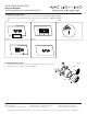
Fig. 7
BLACK
PURPLE
GREY
GREEN
WHITE
Hot
Neutral
Ground
Table 3. Use template supplied to make appropriate cutout for trim installation.
MODEL TRIM CUTOUT INVISIBLE TRIM™ CUTOUT
MT-4LD116N* MT-4LD116T* 5 1/8” X 5 1/8” MT-4LD116TL-WT 5 1/8” X 5 1/8”
MT-4LD216N* MT-4LD216T* 9 3/4” X 5 1/8” MT-4LD216TL-WT 9 3/4” X 5 1/8”
MT-4LD316N* MT-4LD316T* 14 1/2” X 5 1/8” MT-4LD316TL-WT 14 1/2” X 5 1/8”
MT-4LD416N* MT-4LD416T* 19 1/8” X 5 1/8” MT-4LD416TL-WT 19 1/8” X 5 1/8”
MT-4LD226N* MT-4LD226T* 9 3/4” X 9 3/4” MT-4LD226TL-WT 9 3/4” X 9 3/4”
TO INSTALL TRIM
1. When installing in drywall, cut a hole in the drywall (see Table 3 for cut out size).
After nished, if necessary, adjust the xture for ceiling thickness by loosening the screws that attach the square housing to the plaster
frame (Fig. 8).
2. Raise the trim to the housing and attach two sides by securing the tension spring in the anchor cleat (as Fig.9, Fig.10).Push the trim ush
up against the ceiling (Fig.11).
Fig. 9 Fig. 10 Fig. 11
Fig. 8