
User manual


Sending Serial Commands and Data
When sending commands to the meter, a string containing at least one
command character must be constructed. A command string consists of a
command character, a value identifier, numerical data (if writing data to the
meter) followed by a command terminator character, * or $.
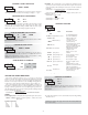
Command Chart
Register Identification Chart
ID Value Description MNEMONIC Transmit Details (T and V)
A Counter A CTA
6 digit positive/5 digit
negative (with minus sign)
B Counter B CTB 5 digit, positive only
C Rate RTE 5 digit, positive only
D Scale Factor A SFA 6 digit, positive only
E Scale Factor B SFB 6 digit, positive only
H
G
F
CLD
SP2
SP1
6 digit positive/5 digit
negative (with minus sign)
per setpoint Assignment,
same as Counter or Rate
per setpoint Assignment,
same as Counter or Rate
T, V, R
T, V, R
T
T, V
T, V
T, V, R
T, V, R
T, V, R
Command String Construction
The command string must be constructed in a specific sequence. The meter
does not respond with an error message to illegal commands. The following
procedure details construction of a command string:
1. The first 2 or 3 characters consist of the Node Address Specifier (N) followed
by a 1 or 2 character node address number. The node address number of the
meter is programmable. If the node address is 0, this command and the node
address itself may be omitted. This is the only command that may be used in
conjunction with other commands.
2. After the optional address specifier, the next character is the command
character.
3. The next character is the register ID. This identifies the register that the
command affects. The P command does not require a register ID character. It
prints all the active selections chosen in the Print Options menu parameter.
4. If constructing a value change command (writing data), the numeric data is
sent next.
5. All command strings must be terminated with the string termination
characters * or $. The meter does not begin processing the command string
until this character is received. See timing diagram figure for differences in
meter response time when using the * and $ terminating characters.
Command String Examples:
1. Node address = 17, Write 350 to the Setpoint 1 value
String: N17VF350*
2. Node address = 5, Read Counter A, response time of 50 msec min
String: N5TA*
3. Node address = 0, Reset Setpoint 1 output
String: RF*
4. Node address = 31, Request a Block Print Output, response time of 2 msec min
String: N31P$
Transmitting Data to the Meter
Numeric data sent to the meter must be limited to transmit details listed in the
Register Identification Chart. Leading zeros are ignored. Negative numbers
must have a minus sign. The meter ignores any decimal point and conforms the
number to the scaled resolution. (For example: The meter’s scaled decimal point
position is set for 0.0 and 25 is written to a register. The value of the register is
now 2.5. In this case, write a value of 250 to equal 25.0).
Note: Since the meter does not issue a reply to value change commands, follow
with a transmit value command for readback verification.
Applicable
Commands
Initiates a block print output. Registers in the
print block are selected in Print Options.
Block Print Request
(read)
P
Reset a count value or setpoint output. Must
be followed by a register ID character
ResetR
Write to register of the meter. Must be
followed by a register ID character and
numeric data.
Value Change (write)V
Read a register from the meter. Must be
followed by a register ID character.
Transmit Value (read)T
Address a specific meter. Must be followed
by one or two digit node address. Not
required when node address = 0.
Node (meter)
Address Specifier
N
NotesDescriptionCommand
set to 9600 baud. This is the factory default setting, so a new meter should
arrive ready for copying. The meter sending the program settings (master)
should be set to the desired baud rate for the application (if different than
9600). This baud rate setting will then be copied to the receiver(s).
Copy Connections:
To connect the LD meters for copying, refer to section 3.5 Serial Wiring for
details. The meter shown in the figures as LD METER will be the master.
1. RS232 - Allows copying from the master meter to a single receiver only.
2. RS485 - Allows copying from the master meter to one or more receivers
simultaneously. Up to 31 receiving meters can be connected during copying.
Copy Procedure:
1. Connect the master and receiver(s) using RS232 or RS485 terminals.
2. Apply power to the meters. The receiving meter(s) must be operating in the
normal display mode (not programming mode).
3. On the master meter, proceed to the Copy Program Settings parameter and
select to begin copying.
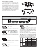
4. During the copy process (~ 2 sec.), the master meter displays an upload message
() while the receiver(s) displays a download message (). This
indicates successful communication between the master and receiver(s).
5. When copying is completed, all receivers display the power-up sequence and
return to normal operating mode, programmed with all the same settings as
the master meter. The master remains at the prompt, ready for another
receiver(s) to be connected for copying.
Setpoint 1
(Reset Output 1)
Setpoint 2
(Reset Output 2)
Counter A Count
Load Value
Receiving Data From The Meter
Data is transmitted from the meter in response to either a transmit command
(T), a block print request command (P) or a User Input print request. The
response from the meter is either a full field transmission or an abbreviated
transmission, depending on the selection chosen in Module 5.
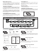
Full Field Transmission
* These characters only appear in the last line of a block print.
The first two characters transmitted are the meter address. If the address
assigned is 0, two spaces are substituted. A space follows the meter address field.
The next three characters are the register mnemonic, as shown in the Register
Identification Chart.
The numeric data is transmitted next. The numeric field (bytes 7 to 18) is 12
characters long. When a requested counter or rate value exceeds the meter’s
display limits, an * (used as an overflow character) replaces a space in byte 7.
Byte 8 is always a space.
The remaining ten positions of this field consist of a minus sign (for negative
values), a floating decimal point (if applicable), and eight positions for the
requested value. The data within bytes 9 to 18 is right-aligned with leading
spaces for any unfilled positions.
The end of the response string is terminated with a <CR> and <LF>. After the
last line of a block print, an extra <SP>, <CR> and <LF> are added to provide
separation between the print blocks.
Byte Description
1, 2 2 byte Node Address field [00-99]
3 <SP> (Space)
4-6 3 byte Register Mnemonic field
7-18
19 <CR> (carriage return)
20 <LF> (line feed)
21 <SP>* (Space)
22 <CR>* (carriage return)
23 <LF>* (line feed)
12 byte data field; 10 for number, one for sign, one for decimal point
14