
User manual


3
3.0 WIRING THE METER
2.0 SETTING THE DIP SWITCHES
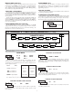
SETTING THE 8 DIP SWITCHES
To access the switches, remove the right side plate of the meter. A bank of
eight switches is located inside the unit.
Warning: Exposed line voltage exists on the circuit boards.
Remove all power to the meter and load circuits before accessing
inside of the meter.
SWITCH 1 (Input A)
LOGIC: Input A trigger levels V
IL
= 1.25 V max.; V
IH
= 2.75 V min.;
V
MAX
= 28 VDC
MAG: 200 mV peak input sensitivity; 100 mV hysteresis; maximum voltage:
40 V peak (28 Vrms); Must also have SRC switch ON. (Not recommended
with counting applications.)
SWITCH 2 (Input A) {See Note 1}
SNK.: Adds internal 7.8 K pull-up resistor to +12 VDC, I
MAX
= 2.1 mA.
SRC.: Adds internal 3.9 K pull-down resistor, 7.2 mA max. @ 28 VDC max.
SWITCH 3 (Input A)
HI Frequency: Removes damping capacitor and allows max. frequency.
LO Frequency: Adds a damping capacitor for switch contact bounce. Limits
input frequency to 50 Hz and input pulse widths to 10 msec.
SWITCH 4 (Input B) {See Note 1}
SNK.: Adds internal 7.8 K pull-up resistor to +12 VDC, I
MAX
= 2.1 mA.
SRC.: Adds internal 3.9 K pull-down resistor, 7.2 mA max. @ 28 VDC max.
SWITCH 5 (Input B)
HI Frequency: Removes damping capacitor and allows max. frequency.
LO Frequency: Adds a damping capacitor for switch contact bounce. Limits
input frequency to 50 Hz and input pulse widths to 10 msec.
SWITCH 6 (RESET/USER INPUT) {See Note 1}
SNK.: Adds internal 7.8 K pull-up resistor to +12VDC, I
MAX
= 2.1 mA.
SRC.: Adds internal 3.9 K pull-down resistor, 7.2 mA max. @ 28 VDC max.
SWITCH 7 (POWER UP RESET)
ENABLE: In this position, the counter resets to zero at power up.
DISABLE: In this position, the counter does not reset at power up.
Note: This switch has no function for programmable models. Power-up reset is
selected through a programming parameter.
SWITCH 8 (Input B)
DIRECTION CONTROL: In this position Input B is used to control the
count direction of Input A when Input A is set to Count with Direction
mode (default mode).
INTENSITY ADJUST: In this position Input B is used to adjust the
LED intensity. There are five distinct LED levels that can be changed by
pulsing Input B. After setting the desired intensity, move switch to
OFF position for Direction Control. Units with keypads can program the
LED intensity level using Programming Menu 3.
Note 1: When the DIP switch is in the SNK position (OFF), the input is
configured as active low. When the switch is in the SRC position (ON), the
input is configured as active high.
3
4
5
6
7
8
ON
SNK.
HI FREQ.
HI FREQ.
Reset/User Input SNK.
Pwr Up Reset DISABLE
Input B Direction Control
SRC.
LO FREQ.
LO FREQ.
SRC.
ENABLE
Intensity Adjust
Factory Setting
2
1
SNK.
LOGIC
SRC.
MAG.
Input A
Input B
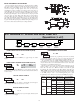
EMC INSTALLATION GUIDELINES
Although this meter is designed with a high degree of immunity to Electro-
Magnetic Interference (EMI), proper installation and wiring methods must be
followed to ensure compatibility in each application. The type of the electrical
noise, source or coupling method into the meter may be different for various
installations. The meter becomes more immune to EMI with fewer I/O
connections. Cable length, routing, and shield termination are very important
and can mean the difference between a successful or troublesome installation.
Listed below are some EMC guidelines for successful installation in an
industrial environment.
1. The meter should be properly connected to protective earth.
2. Use shielded (screened) cables for all Signal and Control inputs. The shield
(screen) pigtail connection should be made as short as possible. The
connection point for the shield depends somewhat upon the application.
Listed below are the recommended methods of connecting the shield, in order
of their effectiveness.
a. Connect the shield only at the panel where the unit is mounted to earth
ground (protective earth).
b. Connect the shield to earth ground at both ends of the cable, usually when
the noise source frequency is above 1 MHz.
c. Connect the shield to common of the meter and leave the other end of the
shield unconnected and insulated from earth ground.
3. Never run Signal or Control cables in the same conduit or raceway with AC
power lines, conductors feeding motors, solenoids, SCR controls, and
heaters, etc. The cables should be ran in metal conduit that is properly
grounded. This is especially useful in applications where cable runs are long
and portable two-way radios are used in close proximity or if the installation
is near a commercial radio transmitter.
4. Signal or Control cables within an enclosure should be routed as far as possible
from contactors, control relays, transformers, and other noisy components.
5. In extremely high EMI environments, the use of external EMI suppression
devices, such as ferrite suppression cores, is effective. Install them on Signal
and Control cables as close to the unit as possible. Loop the cable through the
core several times or use multiple cores on each cable for additional protection.
Install line filters on the power input cable to the unit to suppress power line
interference. Install them near the power entry point of the enclosure. The
following EMI suppression devices (or equivalent) are recommended:
Ferrite Suppression Cores for signal and control cables:
Fair-Rite # 0443167251 (RLC# FCOR0000)
TDK # ZCAT3035-1330A
Steward # 28B2029-0A0
Line Filters for input power cables:
Schaffner # FN610-1/07 (RLC# LFIL0000)
Schaffner # FN670-1.8/07
Corcom # 1 VR3
Note: Reference manufacturer's instructions when installing a line filter.
6. Long cable runs are more susceptible to EMI pickup than short cable runs.
Therefore, keep cable runs as short as possible.
7. Switching of inductive loads produces high EMI. Use of snubbers across
inductive loads suppresses EMI.
Snubber: RLC# SNUB0000.