
User manual


5
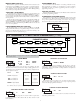
3.4 INPUT WIRING
The Large Display has two signal inputs, A and B. These inputs are wired to
terminal block TBB located inside the unit on the right side.
Terminal 1: Input A
Terminal 3: Input B
Terminal 2: Input Common
Programmable models LD2006P0 and LD4006P0 provide a choice of eight
different Count Modes. The Count Mode selected determines the action of
Inputs A and B. Section 5.1, Input Setup Parameters, provides details on count
mode selection and input action.
All other models are non-programmable and provide Count with Direction
Mode only. Input A accepts the count signal, while Input B controls the count
direction (up/down).
Input B can also be used to adjust the LED display intensity by setting DIP
Switch 8 to the ON position (See Section 2.0, Setting the DIP Switches). For
programmable models, this only applies in Count with Direction mode.
CAUTION: User common is NOT isolated from input common. In order to preserve the safety of the meter application, the DC common must be suitably
isolated from hazardous live earth referenced voltage; or input common must be at protective earth ground potential. If not, hazardous voltage may
be present at the User Input and Input Common terminals. Appropriate considerations must then be given to the potential of the input common with
respect to earth ground.
2
1
ON
3 4
MAGNETIC PICKUP
+EXC
INP A
INP B
INP COMM
1
2
3
4
TBB
COMM
RESET/USER
5
6
COMM
7
to 2.5 mA MAX.
Resistor to
ON
1
2
3
4
AC
COMM
7
COMM
RESET/USER
INP COMM
INP B
+EXC
4
6
5
3
2
INP A
1
TBB
limit current
1
2
ON
3 4
2.2 kΩ
COMM
7
COMM
RESET/USER
INP COMM
INP B
+EXC
4
6
5
3
2
INP A
1
TBB
2
1
ON
34
O.C.
NPN
COMM
7
COMM
RESET/USER
INP COMM
INP B
+EXC
4
6
5
3
2
INP A
1
TBB
1
2
3
ON
4
O.C.
PNP
COMM
7
COMM
RESET/USER
INP COMM
INP B
+EXC
4
6
5
3
2
INP A
1
TBB
1
2
34
ON
COMMON
+5 V
COMM
7
COMM
RESET/USER
INP COMM
INP B
+EXC
4
6
5
3
2
INP A
1
TBB
2
1
ON
3 4
COMM
7
COMM
RESET/USER
INP COMM
INP B
+EXC
4
6
5
3
2
INP A
1
TBB
1
2
3
ON
4
COMM
7
COMM
RESET/USER
INP COMM
INP B
+EXC
4
6
5
3
2
INP A
1
TBB
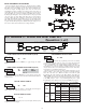
AC Inputs From Tach Generators, Etc.
Input A
Two Wire Proximity, Current Source
Input A
Magnetic Pickup
Input A
Current Sourcing Output
Input A
Interfacing With TTL
Input A
Current Sinking Output
Input A
Switch or Isolated Transistor; Current Sink
Input A
1
2
3 4
ON
COMM
7
COMM
RESET/USER
INP COMM
INP B
+EXC
4
6
5
3
2
INP A
1
TBB
Switch or Isolated Transistor; Current Source
Input A
*
Switch position is application dependent.
Current Sink Output; Quad/Direction
Shaded areas not recommended for counting applications.
LD2006P0 and LD4006P0 only.
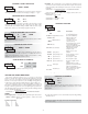
3.5 SERIAL WIRING
TBD
A
COMM
RXD
TXD
4
2
3
1
B
5
232
485
The serial connections are made via terminal block TBD located inside the
unit on the left side for the LD2 and on the right side for the LD4.