
User manual


7
COUNT MODE
Select the count mode that corresponds with your application. The input
actions are shown in the boxes below. For simple counting applications, it is
recommended to use Count with Direction for the count mode. Simply leave the
direction input unconnected.
Counter A SubtractCounter A Add
Counter A AddCounter A Add
Quad ACount A
Quad ACount A
Quad ACount A
Counter B AddCounter A Add
Counter A AddRate only
Counter A DirectionCounter A
INPUT B ACTIONINPUT A ACTION
2 Input Add/Subtract
2 Input Add/Add
Quadrature x4
Quadrature x2
Quadrature x1
Dual Counter
Rate/Counter
Count with Direction
DISPLAY MODE
Note: The Rate indicator signal is derived from Input A in all count modes.
MODULE MENU (PAR KEY)
Each module has a separate module menu (which is shown at the start of each
module discussion). The PAR key is pressed to advance to a particular parameter
to be changed, without changing the programming of preceding parameters.
After completing a module, the display will return to . Programming
may continue by accessing additional modules.
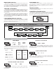
SELECTION / VALUE ENTRY
For each parameter, the display alternates between the present parameter and
the selections/value for that parameter. The SEL and RST keys are used to
move through the selections/values for that parameter. Pressing the PAR key,
stores and activates the displayed selection/value. This also advances the meter to
the next parameter.
For numeric values, the value is displayed with one digit flashing (initially the
right most digit). Pressing the RST key increments the digit by one or the user
can hold the
RST key and the digit will automatically scroll. The SEL key
will select the next digit to the left. Pressing the PAR key will enter the value and
move to the next parameter.
PROGRAMMING MODE EXIT (PAR KEY)
The Programming Mode is exited by pressing the PAR key with
displayed. This will commit any stored parameter changes to memory and return
the meter to the Display Mode. (If power loss occurs before returning to the
Display Mode, verify recent parameter changes.)
PROGRAMMING TIPS
It is recommended to start with Module 1 for counting or Module 2 for rate.
When programming is complete, it is recommended to record the parameter
programming and lock out parameter programming with the user input or
programming security code.
FACTORY SETTINGS
Factory Settings may be completely restored in Module 3. This is useful when
encountering programming problems.
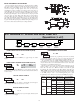
ALTERNATING SELECTION DISPLAY
In the explanation of the modules, the following dual display with arrows will
appear. This is used to illustrate the display alternating between the parameter
on top and the parameter’s Factory Setting on the bottom. In most cases,
selections and values for the parameter will be listed on the right.
Indicates Program Mode Alternating Display
Factory Settings are shown.
Parameter
Selection/Value
PAR
Dual Count or Batch
Only
Counter B
Scale Factor
Counter A
Reset Action
Counter A
Decimal Point
Count
Mode
Counter B
Decimal Point
Counter A
Scale Factor
Dual Count or
Batch Only
Counter B
Batch Count
Enable
Counter A
Count Direction
Counter Reset
at Power-up
User Input
Function
User Input
Assignment
Counter A
Count Load
Value
1-INP
Pro
b-ScF
A-rSt
A-Scf
INP Ab
A-dPt
b-dPt
b-bAt
Cnt LdA-dir
USrINPr P-UP
USrASN
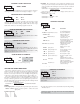
5.1 MODULE 1 - INPUT SETUP PARAMETERS ()
PARAMETER MENU
Shaded area selections only apply when Counter B is enabled (Dual Count
mode or batch counter).
COUNTER A DECIMAL POINT POSITION
This selects the decimal point position for Counter A and the setpoint value,
if assigned to Counter A. The selection will also affect Counter A scale
factor calculations.
COUNTER A SCALE FACTOR
The number of input counts is multiplied by the scale factor to obtain the
desired process value. A scale factor of 1.0000 will result in the display of the
actual number of input counts. (Details on scaling calculations are explained at
the end of this section.)*
to
COUNTER A RESET ACTION
When Counter A is reset, it returns to Zero or Counter A Count Load value.
This reset action applies to all Counter A resets, except a Setpoint generated
Counter Auto Reset programmed in Module 4.
COUNTER A COUNT DIRECTION
Reverse () switches the normal Counter A count direction shown in the
Count Mode parameter chart.