UR3274 Controller User manual Version 1.
Summary 1 2 3 4 5 6 7 Safety instructions............................................................................ 5 1.1 General instructions............................................................... 5 1.2 Intended Usage ....................................................................... 6 1.3 Qualified personnel................................................................ 6 1.4 Remaining hazards ................................................................ 6 1.5 CE Conformity.........
7.10 LATCH ON Functions.............................................................20 7.11 Digital Input Functions........................................................22 7.12 Dual Action Heating-Cooling.............................................23 8 Timer operation...............................................................................25 8.1 Single Timer............................................................................26 8.2 Dual Timer..................................................
Introduction Dear valued Customer! Thank you for purchasing and using a product from our company. The compact universal controller UR3274U integrates in a single device multiple options for sensor reading and actuators command in addition to the extended supply range 24 to 230 Vac/Vdc. With 17 selectable sensors and outputs configurable as relay or SSR command the user can reduce stock needs. The series includes also a model with serial communication RS485 Modbus RTU.
1.2 Intended Usage Units from the controller series UR3274U are used for displaying and monitoring of process values. Any other use is regarded not in accordance with the intended usage. Units from the controller series UR3274U are not meant to be used as sole safety means to prevent dangerous situations on machinery and installations. Machinery and intallations must be so designed that fault conditions can not lead to harmful situations to operating personnel (e.g.
In this manual remaining hazards are marked by the following warning symbol: This symbol indicates that non-observance of the safety guidelines may cause hazards to persons even serious injury or death and/or the possibility of property damage. 1.5 CE Conformity The CE certificate is available at our company. We are pleased to send you a copy of it. Please feel free and contact us to get a copy. 2 Model Identification Refer to the table below to easily select preferred model.
3.2 Hardware Features AN1. Configurable via software. Thermocouple type: K, S, R, J. Automatic compensation of cold junction from 0°C to Analogue 50°C. input Thermoresistance: PT100, PT500, PT1000, Ni100, PTC1K, NTC10K (β 3435K). Linear: 0-10V, 0-20 or 4-20mA, 0-40mV Potentiometers: 6KΩ, 150KΩ, Relay output SSR output Supply 2 relays (UR3274U5) 1 relay (UR3274U6) Configurable as command and/or alarm output 1 SSR Configurable as command output and/ or alarm output. Power supply 24..
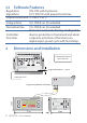
Software Features 3.3 Regulation ON-OFF with hysteresis. algorithms P, PI, PID, PD with proportional time Proportional band 0...9999°C or °F Integral time 0,0...999,9 sec (0 excluded) Derivative time 0,0...999,9 sec (0 excluded) Manual or automatic Tuning, configurable alarms, protection of command and alarm setpoints, activation of functions via digital input, preset cycle with Start/Stop. Controller functions Dimensions and Installation 4 Frontal panel cut-out 28.5 x 70.
Electrical wirings 5 Although this controller was designed to resist electromagnetic interferences in industrial environments, pease observe following safety guidelines: • Separate the feeder line from the power lines. • Avoid placing near units with remote control switches, electromagnetic contactors, high powered motors and in all instances use specific filters. • Avoid placing near power units, particularly if phase controlled. Wiring diagram 5.1 Controller, 2 SW, Relais/SSR Supply: 24...
11 AN1 Analogue Input For thermocouples K, S, R, J.
Examples of Connection for linear input 12 For signals 0….10V • Comply with polarity 0...10V 11 12 For signals 0/4….20mA with three-wire sensor • Comply with polarity C = Sensor output B = Sensor ground A = Sensor power C 0/4...20mA 11 B 9 A PRESSURE TRANSMITTER 12 C For signals 0/4..20mA with external power of sensor • Comply with polarity C = Sensor output B = Sensor ground 0/4...20mA 11 B EXTERNAL SUPPLY PRESSURE TRANSMITTER 12 C For signals 0/4...
Relay Q1 Output 7 Q2 6 Capacity: Q1: 8A, 250Vac,resistive loads,10 5 operations. 30/3A, 250Vac, cosφ=0.3, 10 5 operations. Q2: 5A, 250Vac, resistive loads, 105 operations. 20/2A, 250Vac, cosφ=0.3, 10 5 operations. 5 4 Q1 3 SSR output 8 SSR command output 12V/30mA SSR 9 Digital Input 10 11 Digital input according to parameter DGT.i.
6 Display and Keys Functions 1 9 12 1 2 3 M T R 10 3 6.1 1 2 6.2 4 5 6 11 7 8 2 Numeric Indicators (Display) Normally displays the process. During the 1234 configuration phase, it displays the parameter being inserted. Normally displays the setpoint. During the 1234 configuration phase, it displays the parameter value being inserted. Meaning of Status Lights (Led) 2 ON when the output command is on. For motorised valve command, led is ON when valve is opening and blinks when closing.
6.3 Keys 9 10 11 SET 12 FN C 7 7.1 • Allows to decrease main setpoint. • During configuration phase, allows to slide through parameters. Together with SET key it modifies them. • Pressed after SET key it allows to decrease alarm setpoint. • Allows to increase main setpoint. • During configuration phase, allows to slide through parameters. Together with SET key it modifies them. • Pressed after SET key it allows to increase alarm setpoint.
7.2 Auto-Tune Tuning procedure calculates the controller parameters and can be manual or automatic according to selection on parameter 46 tune. 7.3 Manual Tuning Manual procedure allows the user greater flexibility to decide when to update PID algorithm work parameters. The procedure can be activated in two ways. • Running Tuning by keyboard: Press FNC key until display 1 shows the writing tune with , display 2 shows on. The display 2 showing oFF, press T led switches on and the procedure begins.
7.5 Soft Start To reach the setpoint the controller can follow a gradient expressed in units (e.g. degree/hour). Enter this gradient on parameter 51 Grad. with the chosen units/hour; only on subsequent activation the controller uses soft start function. Automatic/manual tuning cannot be enabled if the Soft start is active. 7.6 Automatic/Manual Regulation for % Output Control This function allows to select automatic functioning or manual command of the output percentage. Parameter 49 Au.ma.
output percentage command unchanged as generated by the PID immediately before breakage. 7.7 Pre-Programmed Cycle Setpoint Pre-programmed cycle function activates by setting pr.cY. on parameter 48 op.Mo. Controller reaches setpoint1 basing on the gradient set on parameter 51 Grad., then it reaches max. power up to setpoint2. When the process reaches max. power, this setpoint is maintained for the time set on parameter 52 ma.t.i.
Insert the programming module when the controller is off. On activation display 1 shows memo and display 2 show ---- (Only if the correct values are saved in the programkey display 2 shows ming module). By pressing the Load, then confirm using the FNC key. The controller loads the new data and starts again. • With the controller not connected to power supply. The programming module is equipped with an internal battery with an autonomy of about 1000 uses.
Press 1 2 3 FN C for 3 sec. or Effect Do Display 1 shows 0000 with the 1st digit flashing, while display 2 shows pass Change the flashing digit and move to the Enter password 9999 next one using the SET key. Instrument loads SET to confirm default settings Turn off and restart the instrument 7.10 LATCH ON Functions For use with input Pot.1 (potentiometer 6KΩ) and Pot.2 (potentiometer 150KΩ) and with linear input (0…10V, 0...
For the calibration procedure refer to the following table: Press Effect Do Place the sensor on the Exit parameters minimum functioning 1 FNC configuration. Display 2 value (associated with shows the writing Latc. Lo.L.i.) Place the sensor on the Set the value to maximum functioning 2 minimum. position The display shows Low (associated with up.L.i.) To exit standard Set the value to procedure press FNC . maximum. For “virtual zero” 3 The display shows HiGt settings place the sensor on zero point.
7.11 Digital Input Functions Digital input is programmable for several functions which are useful to simplify controller operability. Select the chosen function on parameter 50 dGt.i. • Hold function (enabled by setting L.c.n.o. or L.c.n.c.) allows to lock the reading of sensors when the digital input is active (useful for wide ranging oscillation on less significant values). During the hold phase, display 2 flashes and shows Lock.
NB: digital input functions are not available with sensors PT100, NI100, NTC, PTC, PT500, PT1000 and potentiometers. 7.12 Dual Action Heating-Cooling UR3274U is suitable also for systems requiring a combined heating-cooling action. ( act.t. = Heat and with a p.b. greater than 0), and one of the alarms (AL.1 or AL. 2) must be configured as cooL. Command output must be connected to the actuator responsible for heat, while the alarm will control cooling action.
Parameter ou.d.b. determines the percentage overlapping between the two actions. For systems in which the heating and cooling output must never be simultaneously active a dead band ( ou.d.b. ≤ 0) can be configured, and viceversa an overlapping ( ou.d.b. > 0). The following figure shows an example of dual action PID (heating-cooling) with t.i. = 0 and t.d. = 0. P.b. x P.b.m. (COOL) ou.d.b < 0 SPV PV P.b. (HEAT) ACTIVE ACTIVE COMMAND OUTPUT (HEAT) ALARM OUTPUT (COOL) P.b. x P.b.m. (COOL) ou.d.
P.b. x P.b.m. (COOL) ou.d.t > 0 SPV P.b. (HEAT) PV ATTIVO ACTIVE COMMAND OUTPUT (HEAT) ALARM OUTPUT (COOL) ATTIVO ACTIVE Parameter co.t.c. has the same meaning of the cycle time t.c. for heating. Parameter coo.F. (cooling fluid) pre-selects the proportional band multiplier P.b.m. and the cooling PID cycle time co.t.c. basing on the type of cooling fluid: coo.f. P.b.m. co.t.c. Cooling fluid type Air 1.00 10 Air oiL H2o 8 Oil 1.25 4 Water 2.
8.1 Single Timer This option enables one single Timer and the time is selectable by the operator. To achieve this operation set parameter 63 tmr.f. as follows: • s.tm.s. (Single Timer Seconds) time-basis in seconds (mm.ss) • s.tm.m. (Single Timer Minutes) time-basis in minutes (hh.mm) To start/stop the Timer, press FNC for 1 “. During the counting, Led R is On and display2 shows decrementing time.
2 flashes, showing the programmed time until any key is pressed. Start/Stop of Timer by digital input is NOT available for Dual Timer mode. 8.3 Dual Sequential Timer This option enables two Timers and the time is selectable by the operator. At elapsing of Timer 1, counting of Timer 2 will automatically start . At elapsing of Timer 2, counting will stop. To achieve operation of dual sequential Timer set the parameter 63 tmr.f. as follows: • d.s.t.s.
• d.t.L.M. (Double Timer Loop Minutes) time-basis in minutes (hh.mm) To start/stop the Timer, press FNC for 1 “. During the counting, Led R is On (fixed for Timer1, flashing for Timer 2) and display2 shows decrementing time. Start is always made on Timer 1. Start/Stop of Timer is possibile also by digital input, selecting t.1.s.s. on parameter 50 dGt.i. 8.5 Relating Timers to Alarms It is possible to associate the alarms (relay or SSR outputs) to the timers by parameters 23 aL. 1 and 31 aL. 2.
t.2.w.e. Timer 2 Warning Expiring Alarm active for the last 5” of Timer2 Alarm active as long as Timers 1 and 2 t.1.2.s. Timer 1-2 Start Alarm are in Start mode (Timers active) Alarm active at elapsing of Timers 1 and 2 until any key is pressed. Option not t.1.2.e. Timer 1-2 End Alarm available for Dual sequential Timer and Dual Timer Loop. t.1.2.w. Alarm active for the last 5” of Timers 1 Timer 1-2 Warning and 2. expiring 9 9.
At each parameter configuration, instrument storeschange values in the EEPROM memory (100000 writing cycles), while setpoints are stored with a delay of 10 seconds after last modification. NB: modifications made to words different from those described in the following table can lead to instrument malfunction. Modbus RTU protocol features Modbus RTU protocol features Selectable on parameter 56 4.8 k 4800bit/sec 9.6 k 9600bit/sec 19.2k 19200bit/sec Baud-rate 28.8k 28800bit/sec 38.4k 38400bit/sec 57.
6 50 51 500 1000 1001 1002 1003 1004 1005 1006 1007 1008 1009 1010 1011 Boot version Automatic addressing System code comparison Loading default values: 9999 restore all values 9998 restore all values except for baud-rate and slave address 9997 restore all values except for slave address 9996 restore all values except for baud-rate Process (with tenths of degree for temperature sensors; digits for linear sensors) Setpoint1 Setpoint2 Setpoint3 Setpoint4 Alarm1 Alarm2 Setpoint gradient Outputs status (0=of
1012 1013 1014 1015 1016 1017 1018 1019 1100 Manual reset: write 0 to reset all the alarms.
1101 1102 1103 1104 1105 1106 1107 1108 1109 1110 1111 2001 ...
... 3008 3009 ... 3016 3017 3018 3019 3020 3021 ….. Eighth word display1 (ASCII) First word display2 (ASCII) …..
9.2 Master The device works as master if value selected on parameter 59 mast. is other than dis. 9.2.1 Master Mode in retransmission Selecting this mode, the device will write the value to be retransmitted to the address selected on parameter 60 ADD.R on the slave devices having same ID as value selected on parameter 57 SL.AD.
The read/written value might be rescaled according to the proportion described in the following table: Value limits input Limits of rescaled value mast. Min Max Min Max w.pro. Write Process r.w.co. Read/Write Command Setpoint w.ou.p. Write Output Percentage r.w.a.1 Read/Write Alarm 1 Lo.L.i. up.L.i. Lo.L.r. up.L.s. Lo.L.r. up.L.r. Lower Limit Upper Limit Lower Upper Retransmis- RetransmisLimit Input Limit Input sion sion Lo.L.s. Lower Limit Setpoint Lo.L.r. 0 10000 Lo.L.s. up.L.s.
9.2.2 Master Mode Remote process To enable this function it is necessary to select r.pro. on parameter 59 mast. In this mode the process value on UR3274U is a value read via serial communication. The ID of the slave must be same as value selected on parameter 57 sL.ad. and the word to read is selected on parameter 60 add.r. Two successive pollings will be delayed for the time selected on parameter 57 se.de.
3 4 5 Display 1 shows the first parameter and to confirm display 2 shows the value. Slide up/down or through parameters SET SET + or 6 11 FN C Increase or decrease the value displayed by pressing firstly SET and then an arrow key. End of configuration parameter change. The controller exits from programming. Enter the new data which will be saved on releasing the keys. To change another parameter return to point 4. Table of Configuration Parameters The following table includes all parameters.
UR3274U5 Command Q2 Q1 c.o2 c.o1 c.ssr c.uaL. Q1(opens) Q2(closes) c.o1 c.ssr c.uaL. UR3274U6 Command Q1 SSR Q1(opens) SSR(closes) SSR Sensor 2 SEN. analogue input configuration. Tc. k Tc-K -260…1360°C > Default Tc. s Tc-S -40…1760°C Tc. r Tc-R -40…1760°C Tc. J Tc-J -200…1200°C pt PT100 -200…600°C pt 1 PT100 -200…140°C ni NI100 -60…180°C ntc NTC10K -40…125°C ptc PTC1K -50…150°C pts PT500 -100…600°C pt1k PT1000 -100…600°C 0.10 0…10Volt 0.20 0…20mA 4.20 4…20mA 0.40 0…40mVolt pot.1 Potenz.Max 6KΩ F.S.
3 d.p. Decimal Point select number of displayed decimal points. 0 > Default 0.0 0.00 0.000 4 Lo.L.s. Lower Limit Setpoint lower limit setpoint. -999…+9999 [digit3] (degrees.tenths for temperature sensors) Default: 0. 5 UP.L.S. Upper Limit Setpoint upper limit setpoint. -999…+9999 [digit3] (degrees.tenths for temperature sensors) Default: 1750. 6 Lo.L.i. Lower Linear Input lower range limit AN1 only for linear input. -999…+9999 [digit3] Default: 0. 7 up.L.i.
9 o.caL. Offset Calibration number added to process value visualized on display (usually correcting the ambient temperature value). -999…+1000 [digit3] for linear sensors and potentiometers. -99.9…+100.0 (degrees.tenths for temperature sensors). > Default: 0.0. 10 G.caL. Gain Calibration this % is multiplied with displayed value to calibrate the process value. -99.9%…+100.0% > Default: 0.0 11 act.t. Action type regulation type heat Heating (N.A.) > Default cooL, Cooling (N.C.) H.o.o.s.
15 c. HY. Command Hysteresis hysteresis in ON/OFF or dead band in P.I.D. -999…+999 [digit3], (degrees.tenths for temperature sensors) > Default: 0.0 16 c. de. Command Delay (only in ON/OFF functioning).(In case of servo valve it also functions in PID and represents the delay between the opening and closure of the two contacts). -180…+180 seconds, tenths of second in case of servo valve. Negative: delay in switching off phase. Positive: delay in activation phase. Default: 0. 17 c. s.p.
21 t.c. Cycle Time Cycle time for time-proportioning output (10/15sec for PID contactors, 1 sec for PID on SSR or value declared by manufacturer for motorised valves) 0.1-300.0 sec. > Default: 10.0. For motorised valve min. time is 1.0 sec 22 o.po.L. Output Power Limit limit of output power %. 10-100 % > Default: 100 23 aL. 1 Alarm operating mode for Alarm 1. Intervention of the alarm is associated to AL1. dis. Disabled > Default a. aL. Absolute Alarm (see par. 12) b. aL. Band Alarm (see par. 12) H.d.aL.
24 a.1.s.o. Alarm 1 State Output alarm 1 output contact and intervention type n.o. s. (n.o. start) Normally open, active at start > Default n.c. s. (n.c. start) Normally closed, active at start. n.o. t. (n.o. threshold) Normally open,active on reaching alarm4. n.c. t. (n.c. threshold) Normally closed on reaching alarm4. 25 a.1.re. Alarm 1 Reset type of Reset for contact of alarm 1. a.re. Automatic Reset > Default m.re. Manual Reset m.re.s. Manual Reset Stored 26 a.1.s.e.
30 a.1.s.p. Alarm 1 Setpoint Protection does not allow the user to modify setpoint. Free > Default Lock. Locked Hide Locked and hidden 31 aL. 2 Alarm 2 Alarm 2 selection. Alarm intervention is associated to AL2. dis. Disabled > Default a. aL. Absolute Alarm b. aL. Band Alarm H.d.aL. High Deviation Alarm L.d.aL. Low Deviation Alarm a.c.aL. Absolute Command setpoint Alarm st.aL. Start Alarm, Attivo in Run CooL Cooling t.1.s.a. Timer 1 Start Alarm t.1.e.a. Timer 1 End Alarm t.1.w.e. Timer 1 Warning Expiring t.
33 a.2.re. Alarm 2 Reset type of Reset for contact of alarm 2. a.re. Automatic Reset > Default m.re. Manual Reset m.re.s. Manual Reset Stored 34 a.2.s.e. Alarm 2 State Error state of contact for alarm 2 output in case of error. n.o. > Default n.c. 35 a.2.Ld. Alarm 2 Led state of OUT2 led corresponding to relative contact. n.o. n.c. > Default 36 a.2.HY. Alarm 2 Hysteresis -999…+999 [digit7], (degrees.tenths for temperature sensors). > Default: 0. 37 a.2.de. Alarm 2 Delay -180…+180 Sec. > Default: 0.
air oiL H2o Air > Default Oil Water 40 p.b.m. Proportional Band Multiplier 1.00-5.00 > Default: 1.00. 41 ov.d.b. Overlap/Dead Band overlapping/Dead band -20.0-50.0% > Default: 0. 42 co.t.c. Cooling Cycle Time cycle time for cooling output. 1-300 sec. > Default: 10. 43 c.fLt. Conversion Filter ADC filter, number of means on analogue-digital conversions. dis. Disabled 2. s.m. 2 Samples Mean 3. s.m. 3 Samples Mean 4. s.m. 4 Samples Mean 5. s.m. 5 Samples Mean 6. s.m. 6 Samples Mean 7. s.m. 7 Samples Mean 8.
44 c.frn. Conversion Frequency Frequency of sampling for analogue-digital converter. 242H. 242 Hz Max ADC conversion frequency 123H. 123 Hz 62 H. 62 Hz 50 H. 50 Hz 39 H. 39 Hz 33.2H. 33.2 Hz 19.6H. 19.6 Hz 16.7H. 16.7 Hz > Default 12.5H. 12.5 Hz 10 H. 10 Hz 8.33H. 8.33 Hz 6.25H. 6.25 Hz 4.17H. 4.17 Hz Min. ADC conversion frequency 45 v.fLt. Visualization Filter slow down the refresh of display in order to simplify the reading (keeping unchanged the ADC conversion frequency) dis.
46 tune Tune tuning type selection dis. Disabled > Default auto Automatic. PID parameters are calculated at each activation and/or change of setpoint. man. Manual. Launch by keyboard or by digital input. 47 s.d.tu. Setpoint Deviation Tune select the deviation from the command setpoint as threshold used by Autotuning to calculate PID parameters. 0-5000 [digit7], (degrees.tenths for temperature sensors) > Default: 10. 48 op.mo. Operatine Mode select operating mode cont. Controller > Default pr.cY.
rn.n.c. Run n.c. L.c.n.o. Lock Conversion n.o. (Lock visualisation on display with N.O. contact) L.c.n.c. Lock Conversion n.c. (Lock visualisation on display with N.C. contact) tune Tune > Manual a.ma.i. Automatic Manual impulse a.ma.c. Automatic Manual Contact t.1.s.s. Timer 1 Start Stop 51 Grad. Gradient Rising gradient for soft start or pre-programmed cycle 0 Disabled > Default: 0. 1-9999 Digit/time7 (degrees/hours with display of tenths if temperature) 52 ma.ti.
aLL. All (modify all parameters for pre-programmed cyle) 54 vi.tY. Visualization Type select visualization for display 1 and 2 1.p.2.s. 1 Process, 2 Setpoint > Default 1.p.2.H. 1 Process, 2 Hide after 3 sec. 1.s.2.p. 1 Setpoint, 2 Process. 1.s.2.H. 1 Setpoint, 2 Hide after 3 sec. 55 deGr. Degree select degree type c Celsius > Default F Fahrenheit 56 bd.rt. Baud Rate select baud rate for serial communication 4.8 k 9.6 k 19.2k 28.8k 38.4k 57.6k > Default 57 sL.ad.
59 mast. Master select master mode. dis. Disable > Default w.pro Write Process r.w.co. Read Write Command Setpoint w.ou.p. Write Output Percentage r.w.a.1 Read Write Alarm 1 Setpoint r.pro. Read Process 60 add.r. Address Retransmission select address for retransmission. 0x0000 – 0xFFFF hexadecimal > Default: 0x03E9. 61 Lo.L.r. Lower Limit Retransmission lower limit retransmission range. -999 - 9999 [digit8], (degrees for temperature sensors) > Default: 0. 62 up.L.r.
d.t.L.s. s.tm.m. d.tm.m. d.s.t.m. d.t.L.m. Double Timer Loop Seconds Single Timer Minutes Double Timer Minutes Double Sequential Timer Minutes Double Timer Loop Minutes 64 Fa.Gr. Falling Gradient cooling gradient for pre-programmed cycle 0 desabled (uncontrolled cooling) > Default: 0. 1-9999 degrees/hour, with display of tenths 12 Alarm Intervention Modes Absolute Alarm or Threshold Alarm (a. aL. selection) Pv. Absolute alarm with conAlarm Spv troller in heating functioHysteresis ning (Par.11 act.t.
Time Pv Hysteresis parameter > 0 Alarm Spv On Off On Off Alarm output Time Pv Alarm Spv Hysteresis parameter < 0 On Off On Off Alarm output Absolute alarm with controller in cooling functioning (Par.11 act.t. selected cooL) and hysteresis value greater than “0” (Par.28 a.1.Hy. > 0). Absolute alarm with controller in cooling functioning (Par.11 act.t. selected cooL) and hysteresis value less than “0” (Par.28 a.1.Hy. > 0).
NB: The example refers to alarm 1; the function can also be enabled for alarm 2 on model that include it. Band Alarm (b. aL. selection) Pv Alarm Spv Hysteresis parameter > 0 Alarm Spv Command Spv Time Off Off Alarm output Band alarm hysteresis value greater than “0” (Par.28 a.1.Hy. > 0). NB: The example refers to alarm 1; the function can also be enabled for alarm 2 on model that include it.
NB: a) The example refers to alarm 1; the function can also be enabled for alarm 2 on model that include it. b) With hysteresis less than “0” ( a.1.Hy. < 0) the segmented line moves above the alarm setpoint. Pv Command Spv Alarm Spv Hysteresis parameter > 0 Time On Off On Off Upper deviation alarm value of alarm setpoint less than “0” and hysteresis value greater than “0” (Par.28 a.1.Hy. > 0).
Hysteresis parameter > 0 Pv. Alarm Spv Command Spv Time On On Off Lower deviation alarm value of alarm setpoint less than “0” and hysteresis value greater than “0” (Par. 28 a.1.Hy. > 0). Alarm output NB: a) The example refers to alarm 1; function can also be enabled for alarm 2 on model that include it. b) With hysteresis value less than “0” ( a.1.Hy. < 0) the dotted line moves under alarm setpoint.
E-06 Off-line in master mode ser.e. remote process E-08 Missing calibration data sYs.e. 14 Check the serial connection, baud-rate and device ID. Call Assistance Summary of Configuration parameters Date: Installer: Notes: c.out sen. d.p. Lo.L.s. up.L.s. Lo.L.i. up.L.i. Latc. o.caL G.caL act.t. c. re. c. s.e. c. Ld. c. HY. c. de. c. s.p. p.b. t.i. t.d.
t.c. o.poL. AL. 1 A.1.s.o. A.1.re. A.1.s.e. A.1.Ld. A.1.Hy. A.1.de. A.1.s.p. aL. 2 A.2.s.o. A.2.re. A.2.s.e. A.2.Ld. A.2.Hy. A.2.de. A.2.s.p. coo.f. p.b.m. ou.d.b. co.t.c. c.fLt. c.frn. v.fLt. tune s.d.tu. op.mo. au.ma. dGt.i. Cycle time Limit of output power % Alarm 1 selection Alarm 1 output contact and intervention type Reset type of alarm 1 contact.
Grad. ma.t.i. u.mc.p. vi.tY. deGr. bd.rt. sL.ad. se.de. mast. add.r. Lo.L.r. up.L.r. tmr.f. fa.Gr.
Wachendorff Prozesstechnik GmbH & Co. KG Industriestrasse 7 • D-65366 Geisenheim Tel: +49 (0) 67 22 / 99 65 - 20 Fax: +49 (0) 67 22 / 99 65 - 78 E-Mail: efdi@wachendorff.de www.wachendorff-prozesstechnik.de © Copyright by Wachendorff Prozesstechnik GmbH & Co.