
User manual


UR3274U - User manual 13
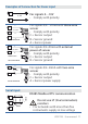
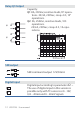
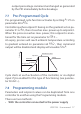
Display and Keys Functions
5
4
3
8
7
6
2
1
M T R
2 3
9
10
12
11
1
. Numeric Indicators (Display)
1234
Normally displays the process. During the
con guration phase, it displays the parameter
being inserted.
1234
Normally displays the setpoint. During the
con guration phase, it displays the parameter
value being inserted.
. Meaning of Status Lights (Led)
1
ON when the output command is on. For
motorised valve command, led is ON when valve is
opening and blinks when closing.
2
ON when alarm is on.
3
ON when alarm is on.
M
ON when the “Manual” function is on.
T
ON when the controller is running an “Autotuning”
cycle.
R
ON when the controller communicates via serial
port.