
Operator`s manual

PUREHEAT™ HYDRONIC AIR HEATER OPERATOR’S MANUAL–SECTION 2
V. 2, Rev. 09/01/06 © 2006 Ground Heaters, Inc. 2- 5
2-5
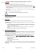
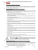
Valve #2
2-6
Valve #1
Valve #3
Valve #4
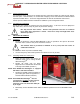
2.2.7 Deployment of Circulation Hoses or Option Heat Transfer Hose
(Applies to Pureheat and Hose Handling Systems HHS3004)
The Hose Reel contains Ten (10) 1 in. ID Red Circulation Hoses with QCs [Four (4) at 50 ft (15 m), Four
(4) at 100 ft (30 m), and Two (2) at 200 ft (61 m)].
1. Release the Hose Reel Brake by turning the Brake T-handle counterclockwise
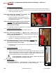
2. Remove the 1 in. ID Red Circulation Hoses with QCs or 5/8 in. ID Black Heat Transfer Hose Loops
(HHS3004) from the Hose Reel. Disconnect each hose Quick-Connect as it is removed from the
Hose Reel.
3. Select the shortest
1 in. ID Red Circulation Hoses and route, one at a time, to provide a supply and
return connection to each Heat Xchanger
TM
or 4-Port Remote Manifold (if applicable) and 5-Port On-
Board Manifold.
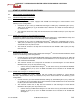
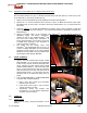
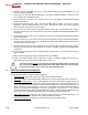
4. Connect Circulation Hoses to the respective Heat Xchanger
TM
or 4-Port Remote Manifold (if
applicable) Supply and Return connections.
Support the QC on the HX200 Xchanger
TM
with
one hand when making these connections to
insure good connection. Ensure hoses lay on top
of HX200 Heat Xchanger
TM
once connection is
made to avoid HTF restrictions.
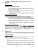
5. The HX50 and the HX100 series Heat
Xchangers
TM
are equipped with 40 ft (12 m) of ½ in
or 5/8 in. ID Black Circulation Hoses permanently
mounted and will connect to the 4-Port Remote
Manifolds. Four (4) HX50 or Two (2) HX100 can be
connected per 4-Port Remote Manifold).
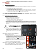
2.3 INITIAL POWER UP
1. Connect the Main Control Panel Pigtail marked
MAIN POWER 1 to an extension cord connected
to one 15 amp 120 volts AC 60 Hz electrical power
circuit. Connect the Main Control Panel Pigtail
marked MAIN POWER 2 Twist-Lock Male cord
end to a Twist-Lock Female cord end extension
cord connected to one 20 amp 120 volts AC 60 Hz
electrical power circuit. Use only heavy-duty 10-3
extension cords of no more than 100 ft (30 m) in
length.
2. Turn the MAIN BREAKER 1 and MAIN BREAKER
2 Switches ON, verify the following:
a. LINE 1 and 2 GFI’s remain reset and Amber
Indicator Lights are OFF.
b. LOW LEVEL FAULT light is ON for fifteen
seconds and then turns OFF.
c. Temperature Control (TC) displays HTF
temperature in red and desired temperature
(set point) in green numbers.
2.4 START UP
2.4.1 Integrity Check
Verify all hose, fittings, and pipe connections are not
leaking.