
Operator`s manual
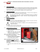

PUREHEAT™ HYDRONIC AIR HEATER OPERATOR’S MANUAL – SECTION 2
2- 6 © 2006 Ground Heaters, Inc. V. 2, Rev. 09/01/06
2-7
2-8
2.4.2 Warming the Heat Transfer Fluid
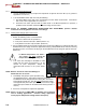
1. Use the UP/DOWN arrow keys to adjust the temperature set-point on the TC to 70°F (21°C). (Refer to
Appendixes A-2 and A-3.)
2. Turn the BURNER Switch ON, then verify the following:
a. The Burner Motor starts (after a five second delay) and fires fifteen seconds later. If the Burner
fails to start, refer to Appendixes A-12 and A-13.
b. The Burner runs clean, quiet and with no
visible smoke. If the Burner operation is in question, a
qualified service technician should check Burner settings and emissions.
NOTE: Section 4.3, BURNER COMBUSTION VERIFICATION AND ADJUSTMENT, provides detailed
instructions for testing Burner emissions and settings.
2.4.3 Initiating Flow through Heat Transfer Hose
(Refer to Appendix B-1.)
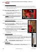
1. Position the following valves as directed below:
a. OPEN the Suction Valve #3. (Photo 2-6)
b. Verify Cross-Connect Valve #5 is OPEN. (Photo 2-13)
c. Verify Return Valve #2 is fully CLOSED. (Photo 2-5)
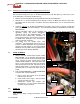
2. Turn the PUMP Switch ON at the Main Control Panel until the Pump Motor has reached full RPM. The
Dashboard Pressure Gauge will read an approximate 50 psig. Slowly OPEN Return Valve #2, lowering
operating pressure, to a minimum of 30 psig on the Dashboard Pressure Gauge for optimum flow rate.
(Photo 2-8)
If ambient temperatures are below -
15ºF (-26ºC), you must
pre-heat the
Pump before turning the Pump ON.
3. Turn each Heat Xchanger™ BLOWER or FAN
Switch ON and verify the thermostat is at the
desired set point temperature. Output air
temperature will increase as the system warms
up.
NOTE: Blowers will not run if the Heat Xchanger™
thermostats are set too low.
4. Periodically verify proper system operation using
the dashboard gauges. Adjust Return Valve #2 so that the
Dashboard Pressure Gauge maintains 30 psig. Min. The Return
Flow Indicator should spin. The HTF return
temperature should
read approximately 40º to 50ºF (22º to 28ºC) less than the supply
temperature (red numbers on the Main Control Panel). (Photo 2-7
and 2-8)
5. Set the TC to temperature required for application.
NOTE: Always set the TC to 180°F (82°C) for thawing, frost prevention
and air heating applications. Concrete curing applications
usually require temperature settings below 180ºF (82ºC).
!