Operator’s Manual Mobile Generator G 25 EN 5000186960 5 0 0 0 06 1 8 0911 6 9 6 0
Copyright notice © Copyright 2011 by Wacker Neuson Production Americas LLC All rights, including copying and distribution rights, are reserved. This publication may be photocopied by the original purchaser of the machine. Any other type of reproduction is prohibited without express written permission from Wacker Neuson Production Americas LLC. Any type of reproduction or distribution not authorized by Wacker Neuson Production Americas LLC represents an infringement of valid copyrights.
G 25 Foreword Foreword SAVE THESE INSTRUCTIONS—This manual contains important instructions for the machine models below. These instructions have been written expressly by Wacker Neuson Production Americas LLC and must be followed during installation, operation, and maintenance of the machines.
Foreword G 25 Manufacturer’s This manual contains references to approved parts, attachments, and approval modifications. The following definitions apply: Approved parts or attachments are those either manufactured or provided by Wacker Neuson. Approved modifications are those performed by an authorized Wacker Neuson service center according to written instructions published by Wacker Neuson. Unapproved parts, attachments, and modifications are those that do not meet the approved criteria.
G 25 1 Foreword 3 Safety Information 9 1.1 1.2 1.3 1.4 1.5 1.6 1.7 2 18 Label Locations .................................................................................. 18 Label Meanings .................................................................................. 20 Lifting and Transporting 3.1 3.2 4 Signal Words Used in this Manual ....................................................... 9 Machine Description and Intended Use .............................................
Table of Contents 4.13 4.14 4.15 4.16 4.17 4.18 4.19 4.20 4.21 4.22 4.23 4.24 4.25 4.26 4.27 5 Warning Light ......................................................................................42 Connection Lugs .................................................................................43 Grounding the Generator ....................................................................44 Convenience Receptacles ...................................................................
G 25 7 Factory-Installed Options 7.1 7.2 7.3 7.4 7.5 7.6 7.7 7.8 7.9 7.10 7.11 8 71 Engine Block Heater Option ............................................................... 71 Automatic LCD Heat ........................................................................... 72 Low Coolant Shutdown ...................................................................... 73 Lube Level Maintainer ........................................................................ 74 Temperature-Activated Shutters ........
Table of Contents G 25 8 wc_bo5000186960_06TOC.
G 25 1 1.1 Safety Information Safety Information Signal Words Used in this Manual This manual contains DANGER, WARNING, CAUTION, NOTICE, and NOTE signal words which must be followed to reduce the possibility of personal injury, damage to the equipment, or improper service. This is the safety alert symbol. It is used to alert you to potential personal hazards. f Obey all safety messages that follow this symbol.
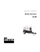
Safety Information 1.2 G 25 Machine Description and Intended Use This machine is a mobile electric power source. The Wacker Neuson Mobile Generator consists of a trailer-mounted cabinet containing an electric alternator, a fuel tank, and a diesel engine. A control panel, receptacles, and connection lugs are provided on the side of the cabinet. As the engine runs, the generator converts mechanical energy into electric power. The operator connects loads to the electric power receptacles and connection lugs.
G 25 Safety Information • Electric shock and arc flash • Personal injury from improper lifting the trailer tongue • Typical hazards related to towing a trailer on roads and highways To protect yourself and others, make sure you thoroughly read and understand the safety information presented in this manual before operating the machine.
Safety Information G 25 • Close-fitting work clothes that do not hinder movement • Safety glasses with side shields • Hearing protection • Safety-toed footwear 1.3.1 Do not operate the generator when open containers of fuel, paint, or other flammable liquids are near. 1.3.2 Do not place flammable material or liquids near the generator. 1.3.3 Do not operate the generator, or tools attached to the generator, with wet hands. 1.3.4 Do not use worn electrical cords.
G 25 Safety Information 1.3.19 Remove all tools, cords, and other loose items from the generator before starting it. 1.3.20 Make sure the machine is well-grounded and securely fastened to a good earthen ground per national and local regulations. WARNING 1.
Safety Information G 25 This will notify everyone that the unit is being serviced and will reduce the chance of someone inadvertently trying to start the unit. If the unit is connected to a remote start or transfer switch, make sure the remote switch is also off and tagged. 1.4.2 Ground Connection The generator must be connected to a good earthen ground for proper operating safety! A central “equipment ground” is provided at the customer connection lugs.
G 25 1.5 Safety Information Operator Safety while Using Internal Combustion Engines WARNING Internal combustion engines present special hazards during operation and fueling. Failure to follow the warnings and safety standards could result in severe injury or death. f Read and follow the warning instructions in the engine owner’s manual and the safety guidelines below. DANGER Exhaust gas from the engine contains carbon monoxide, a deadly poison. Exposure to carbon monoxide can kill you in minutes.
Safety Information 1.6 G 25 Towing Safety Towing a large trailer requires special care. Both the trailer and vehicle must be in good condition and securely fastened to each other to reduce the possibility of an accident. WARNING 1.7 1.6.1 Verify that the hitch and coupling on the vehicle are rated equal to, or greater than, the trailer's “gross vehicle weight rating” (GVWR). 1.6.2 Inspect the hitch and coupling for wear or damage. DO NOT tow the trailer using defective parts. 1.6.
G 25 2 2.1 Labels Labels Label Locations EE E K X I H D GG C F W JJ G G wc_si000518gb.
Labels G 25 J J T B SS TT M RR C DD P D I OO PP JJ CC L KK O N G FF LL MM AA G BB V Ø A HZ OFF AUS APAGADO ARRET Y Basler DIAGNOSTICS DIAGNOSEN DIAGNOSTICOS DIAGNOSTICS REMOTE START START / RUN FERNSTART ARRANQUE REMOTO DEMARRAGE A DISTANCE START / LAUFEN ARRANQUE / MARCHA DEMARRER / MARCHE X R QQ Q1 Q2 Z S V R 18 I wc_si000518gb.
Labels 2.2 Label Meanings A (on trailer, if equipped) TOWING INSTRUCTIONS 1. READ OPERATOR'S MANUAL. 2. USE HITCH RATED FRO TRAILER'S "GROSS VEHICLE WEIGHT RATING". 3. SECURELY ATTACH TRAILER TO TOW VEHICLE. 4. ATTACH SAFETY CHAINS USING CROSS PATTERN. 5. ATTACH BREAKDOWN CHAIN TO VEHICLE. 6. CHECK TRAILER LIGHTS. ABSCHLEPPINSTRUKTIONEN 1. BETRIEBSVORSCHRIFT LESEN. 2. ANHANGEVORRICHTUNG VERWENDEN, DIE DER GESAMTBETRIEBSGEWICHTSKLASSE ENTSPRICHT. 3. ANHANGER SICHER AM ZUGFAHRZEUG BEFESTIGEN. 4.
Labels F G 25 DANGER! Asphyxiation hazard. Engines emit carbon monoxide. Do not run the machine indoors or in an enclosed area unless adequate ventilation, through such items as exhaust fans or hoses, is provided. Read the Operator’s Manual. No sparks, flames, or burning objects near the machine. Stop the engine before refueling. G Tie-down point H WARNING! To prevent hearing loss, wear hearing protection. Hand injury if entangled in moving belt.
G 25 Labels L M Operator’s Manual must be stored on machine. Replacement Operator’s Manual can be ordered through your local Wacker Neuson distributor. N DANGER Danger of asphyxiation! Do not operate this machine indoors. Electric shock and arc flash will cause serious injury or death. wc_si000518gb.
Labels G 25 O WARNING! Generator can automatically start which can cause serious injury. Disconnect battery before servicing. P WARNING! Read and understand the supplied Operator’s Manual before operating the machine. Failure to do so increases the risk of injury to yourself and others. AND Q1 Q2 WARNING! To reduce the risk of electrical shock and arc flash, read the Operator’s Manual.
G 25 Labels T U WARNING! Disconnect battery before servicing. Read the Operator’s Manual. (on trailer, if equipped) V Operator’s Manual must be stored on machine. Replacement Operator’s Manual can be ordered through your local Wacker Neuson distributor. W Drain containment system. X WARNING! To prevent hearing loss, wear hearing protection when operating the machine. WARNING! Pressurized contents. Do not open when hot! WARNING! Hand injury if entangled in moving belt.
Labels G 25 Z Neutral bonded to frame AA Fuses Read the Operator’s Manual for machine information. 1 - Start / Run Circuit 2 - Fuel Pump 3 - Governor 4 - Controller BB WARNING! Electric shock at cooling fins. CC Generator and Receptacle Wiring DD Engine wiring 24 wc_si000518gb.
G 25 Labels EE WARNING! Hot surface FF (if equipped) Battery disconnect must be in “ON” position to start engine. NOTICE: Do not use the battery disconnect switch while engine is running. Damage to the electrical components may occur. GG Low sulfur fuel or ultra low sulfur fuel only. HH Hand hold JJ Protecting Our Environment Fluid containment system KK Diagnostic menu navigation wc_si000518gb.
Labels G 25 LL A nameplate listing the model number, item number, revision number, and serial number is attached to each unit. Please record the information found on this nameplate so it will be available should the nameplate become lost or damaged. When ordering parts or requesting service information, you will always be asked to specify the model number, item number, revision number, and serial number of the unit. MM This machine may be covered by one or more patents.
G 25 Labels RR (Camlock models only) WARNING! Electric shock can cause serious injury or death. SS (Camlock models only) NOTICE Separate overcurrent protection must be provided. Do not exceed 400 amps per receptacle. TT (Camlock models only) WARNING! Electric shock and arc flash can cause serious injury or death. wc_si000518gb.
Labels G 25 Notes: 28 wc_si000518gb.
G 25 3 3.1 Lifting and Transporting Lifting and Transporting Lifting the Machine A central lifting eye is located at the top of the generator and is attached to a lifting frame inside the housing. WARNING 3.2 Crushing / machine damage hazard. Make sure the lifting devices have sufficient capacity to lift the unit safely. Refer to Technical Data for the proper operating weight of the generator. When lifting the generator, attach a hook or sling securely to the lifting eye.
Lifting and Transporting G 25 NOTICE: When towing, maintain extra space between vehicles and avoid soft shoulders, curbs and sudden lane changes. If you have not pulled a trailer before, practice turning, stopping, and backing up in an area away from heavy traffic. DO NOT exceed 55 mph when towing a trailer. In most states, large trailers must be registered and licensed by the State Department of Transportation. Before towing, be sure to check licensing requirements. 30 wc_tx001183gb.
G 25 4 Operation Operation Preparing for first use To prepare your machine for first use: 4.0.1 Make sure all loose packaging materials have been removed from the machine. 4.0.2 Check the machine and its components for damage. If there is visible damage, do not operate the machine! Contact your Wacker Neuson dealer immediately for assistance. 4.0.3 Take inventory of all items included with the machine and verify that all loose components and fasteners are accounted for. 4.0.
Operation 4.1 G 25 Refueling the Machine Requirements • Machine shut down • Engine cool • Machine/fuel tank level with the ground • Fresh, clean fuel supply Procedure Perform the procedure below to refuel the machine. WARNING Fire hazard. Fuel and its vapors are extremely flammable. Burning fuel can cause severe burns. f Keep all sources of ignition away from the machine while refueling. f Refuel only when the machine is outdoors. f Clean up spilled fuel immediately. 4.1.1 Remove the fuel cap.
G 25 4.2 Operation Control Panel Ref. Description Ref.
Operation G 25 2 4 1 6 3 V Ø A HZ OFF AUS APAGADO ARRET REMOTE START START / RUN FERNSTART ARRANQUE REMOTO DEMARRAGE A DISTANCE START / LAUFEN ARRANQUE / MARCHA DEMARRER / MARCHE DIAGNOSTICS DIAGNOSEN DIAGNOSTICOS DIAGNOSTICS R ERGENC M Y E Basler 5 DIAGNOSTICS DIAGNOSEN DIAGNOSTICOS DIAGNOSTICS S TO P 34 wc_tx001045gb.
G 25 4.3 Operation Voltage Selector Switch See Graphic: wc_gr001682 The voltage selector switch is located in a separate enclosure on the generator on the opposite side of the machine. The selector switch is a three-position switch which mechanically changes the connections between the generator output leads and the terminal lugs on the generator. This allows three different volt ranges to be selected. 120/240 VAC 1Ø 120/208 VAC 3Ø 139/240 VAC 3Ø (Refer to Section Voltage Adjustment Rheostat.
Operation Emergency Stop Switch See Graphic: wc_gr006062 The emergency stop switch (p) is the red button located below the receptacle panel and can be accessed with the panel doors closed. Activate the emergency stop switch by pushing the red button in. Pushing the emergency stop switch opens the main circuit breaker and the fuel solenoid, and results in the engine shutting down. The switch will remain activated until the button is pulled out.
G 25 4.5 Operation Main Line Circuit Breaker See Graphic: wc_gr005866 The main line circuit breaker (a) is located on the control panel. In the off “O” position, this breaker interrupts power from the selector switch to the terminal lugs at the bottom of the generator panel. NOTICE: Before shutting down the generator or performing any service to the generator unit, make sure the main circuit breaker is in the off “O” position.
Operation 4.6 G 25 Engine Start Switch See Graphic: wc_gr005866 The engine start switch (f) is a three-position switch: “REMOTE START”, off “O”, and “START/RUN”. The “REMOTE START” position is the normal setting used when using the generator as a back-up power supply connected to a remote switch. In the REMOTE START position, the generator is in stand-by mode and will not start until the remote switch closes.
G 25 4.9 Operation Connection Lugs See Graphic: wc_gr005864 The customer connection lugs (r) are located on left at the bottom of the panel behind a hinged door. The lugs provide connection points for attachment of outside loads. A large label like the one shown in section Terminal Connections is attached to the inside of the terminal door. It shows the correct terminal connections for selected voltages.
Operation 4.10 G 25 Grounding the Generator Location A ground connection is located at the customer connection terminal lugs. wc_gr008288 Function This ground connection is used for electrically grounding the generator when necessary to comply with the National Electrical Code and other federal, state, and local regulations. For grounding requirements in your area, consult with a qualified electrician, electrical inspector, or local agency having jurisdiction over electrical compliance.
G 25 Operation 4.11 Convenience Receptacles See Graphic: wc_gr005864 The generator is equipped with one 120V/240V twist lock receptacle (m) rated at 30A, and one 120V/240V twist lock receptacle (l) rated at 50A. The two 120V duplex receptacles (n) are equipped with ground fault interrupts (GFI). Receptacles do not connect through the main line circuit breaker. Each receptacle is protected by its own circuit breaker (k) which is located directly above it.
Operation G 25 4.14 Terminal Connections ALL CONNECTIONS TO THE TERMINALS MUST BE MADE BY A TRAINED ELECTRICIAN. BACKFEED FROM THE GENERATOR INTO THE UTILITY’S DISTRIBUTION SYSTEM CAN CAUSE A SERIOUS INJURY OR WARNING DEATH TO UTILITY WORKERS! Improper connection of generator to a building’s electrical system can allow electrical current from the generator to backfeed into utility lines. This may result in electrocution of utility workers, fire or explosion.
G 25 Operation 4.15 Before Starting Before putting the generator into service, review each item on the following checklist. Because generators are often run for long periods of time unattended, it is important to make sure that the unit is set up properly to reduce possible problems. WARNING wc_tx001045gb.fm Failure to follow the procedures listed may cause injury to personnel or damage to the generator.
Operation 4.16 G 25 Starting See Graphic: wc_gr001682, wc_gr001677, wc_gr005866 Before starting the generator set, thoroughly review the pre-start-up checklist in the previous section. Proceed with generator start-up only after checking each item in that section. Thoroughly read and make sure you understand the engine operator’s manual supplied with the generator. Follow the steps below and the illustration on the opposite page in the order listed.
G 25 Operation Check that AC voltage is correct. Voltage can be fine-adjusted by turning the voltage adjustment rheostat (b) on the metering panel. 4.16.9 Check frequency. Under no-load conditions, frequency should read around 61.5 Hz, dropping to near 60 Hz as the generator load is switched on. ERGENC M Y E 4.16.
Operation 4.17 G 25 Operation See Graphic: wc_gr005866 Leave the engine start switch (f) in the “START/RUN” position while the generator is operating. If the generator was started using a remote switch, leave engine start switch in the “REMOTE START” position. Let the generator run for a few minutes to warm engine before closing main circuit breaker. WARNING Before closing breakers, make sure that any electrical devices attached downstream from the generator will not start up unexpectedly.
G 25 Operation 4.18 Generator Monitoring Generator information is displayed on the top line of the LCD panel and is scrolled continuously while the generator is operating, to show the voltage, amperage and frequency of each phase. Volts “V”- Displays the AC output voltage being produced by the generator. Phase “Ø” - Indicates which leg is currently being displayed. In threephase mode, the display will read P1, P2, or P3. In single-phase mode, the display will read L1, L3, or LL.
Operation G 25 4.19 Engine Monitoring With the engine start switch set to “RUN/START” or “REMOTE START”, engine information will be continuously displayed on the bottom line of the LCD panel. OIL —Displays engine oil pressure. The gauge registers oil pressure between 0–100 psi. Normal operating pressure is between 60–80 psi. If oil pressure drops below 15 psi, the engine will automatically shut down. FUEL —Indicates the relative fuel level in the fuel tank.
G 25 Operation 4.20 Engine Shutdown Faults The Engine Control Module (ECM) continuously monitors vital engine functions for seven fault conditions. When a fault condition occurs, the engine will shut down and the LCD panel will display the fault causing the shutdown. To reset the ECM and resume operation, return the engine start switch manually to off “O”. Also refer to Section Warning Light. 4.20.1 EMERGENCY STOP Indicates that the emergency stop button has been depressed.
Operation G 25 4.21 Current Overload Fault Along with engine functions, the ECM continuously monitors the current load in each phase. The values for current overload are programmed into the ECM at the factory and are different for each generator size. a V Ø A HZ Basler DIAGNOSTICS DIAGNOSEN DIAGNOSTICOS DIAGNOSTICS d R wc_gr006061 4.21.1 When an overcurrent condition is sensed in any leg, the warning/fault LED (d) will flash and the display will indicate OVERCURRENT. 4.21.
G 25 Operation 4.23 Engine Power Correction Factors Performance data on Isuzu engines are measured at the following standard conditions: • 29.31 inches of mercury dry air pressure • 600 feet altitude • 0 % relative humidity • 77°F air intake temperature • 104°F fuel inlet temperature Refer to the table to estimate the engine power decrease in percent, as environmental factors vary from the standard conditions. MODEL G 25 FUEL TEMP RISE of 1.
Operation 4.26 G 25 Cold Weather Starting Successful cold weather starting requires that the battery be at peak power, the correct weight motor oil is used, and the starter motor is in good condition. The ECM will automatically activate the cold starting aid and will display START DELAY as the glow plugs heat up. 4.
G 25 Operation Note: A cooldown timer is activated once the remote run signal is removed. The cooldown time can be changed if desired. See “Changing Cooldown Time.” 4.28 Remote/Transfer Switch WARNING WARNING When the generator is used as a stand-by power supply, it must be equipped with a device which isolates it from the utility’s distribution system.
Using the LCD Panel and Keypad 5 Mobile Generator Using the LCD Panel and Keypad See graphic: wc_gr005938, wc_gr006064 During normal operation, the LCD panel (e) displays current information on machine performance and operating status. The keypad (g) provides access to additional monitoring functions through a series of menus displayed on the LCD panel. You can also use the keypad to change certain machine settings if desired. . 5.0.
Mobile Generator 5.1 Using the LCD Panel and Keypad Navigating the Menus The label pictured below is a navigational aid to access the various diagnostic menus programmed into the LCD. See the accompanying table for information about the menu items. .
Using the LCD Panel and Keypad Menu Item Alarm Config Description Alarm configuration Mobile Generator Menu Item J1939 Active DTC Description Diagnostic Trouble Codes Alarm Configuration J1939 Data Alarms J1939 Engine Config Engine configuration Alarm–Status J1939 Previous DTC Diagnostic Trouble Codes Amps kVA Back kVAR Battery Volt kW Bias Control Language Breaker Management LCD Contrast Bus Frequency Loaded Run Time Bus V Bus voltage Communications Kilowatts Liquid Crystal Disp
Mobile Generator 5.2 Using the LCD Panel and Keypad Entering Passwords See graphic: wc_gr006068 Some configuration procedures require a password to be entered before changes can be made. Once a password has been entered, it remains in the memory until the machine is shut off. Note: The default password is OP and is set by the factory. Contact your Wacker Neuson dealer if you need to have the password reset. Follow the steps below to enter a password. wc_tx001182gb.fm 5.2.
Using the LCD Panel and Keypad 5.3 Mobile Generator Adjusting Screen Contrast The display contrast of the LCD panel can be adjusted to suit the operator’s preference, or for increased visibility in jobsites with low or bright ambient light. 5.3.1 To access the main menu, press the right arrow button (1) on the keypad (g). Note: If there are active alarms or pre-alarms, press the left arrow button (4) three times to access the main menu. 5.3.
Mobile Generator 5.4 Using the LCD Panel and Keypad Setting the Time or Date See graphic: wc_gr005938 The control module features a clock powered by a separate battery. Follow the steps below to change the time or date. 5.4.1 To access the main menu, press the right arrow button (1) on the keypad (g). Note: If there are active alarms or pre-alarms, press the left arrow (4) three times to access the main menu. wc_tx001182gb.fm 5.4.
Using the LCD Panel and Keypad 5.5 Mobile Generator Changing User Preferences Changing Display Units The LCD panel can be configured by the operator to display system information in either metric units or English units. 5.5.1 To access the main menu, press the right arrow button (1) on the keypad (g). Note: If there are active alarms or pre-alarms, press the left arrow button (4) three times to access the main menu. 5.5.
Mobile Generator 5.6 Using the LCD Panel and Keypad Changing / Disabling Low Fuel Fault See graphic: wc_gr005938 The low fuel fault value can be changed or disabled through the diagnostics menu. (For example, you may wish to reduce the value so that the machine operates for a longer period before running out of fuel.) Note: The engine will shut down if the machine runs out of fuel. Follow the steps below to change or disable the low fuel fault. 5.6.
Using the LCD Panel and Keypad 5.7 Mobile Generator Changing Cooldown Time See graphic: wc_gr005938 A cooldown timer activates when the machine is no longer receiving a remote run signal. This timer is factory set to zero (0) minutes. The cooldown time can be changed if desired. 5.7.1 To access the main menu, press the right arrow button (1) on the keypad (g). Note: If there are active alarms or pre-alarms, press the left arrow (4) three times to access the main menu. 5.7.
G 25 6 Factory-Installed Options Factory-Installed Options This machine may be equipped with one or more of the following factory-installed options. To verify if any of these options are installed on your machine, contact Wacker Neuson Corporation at 1-800-7700957. A nameplate listing the Model Number, Item Number, Revision, and Serial Number is attached to each unit. Please have this information available when contacting Wacker Neuson Corporation.
Factory-Installed Options 6.2 G 25 Fuel/Water Separator See Graphic: wc_gr001705 The fuel/water separator separates water from the fuel on models with Isuzu engines. Empty the separator water bowl (a) as needed by opening the water bowl drain (b). The separator element should be changed each time the fuel filter is changed—approximately every 600 hours of operation. To change the element: 6.2.1 Loosen the element retainer (d) and remove the retainer and element (c) from the separator head. 6.2.
G 25 6.3 Factory-Installed Options Electronic Governor See Graphic: wc_gr005093, wc_gr001717 The electronic governor option consists of an electronic module (a) and an electronic actuator (c). The module senses rotation of the flywheel, then sends a signal to the electronic actuator that governs the fuel injection system. The system is designed to precisely regulate engine rpm, and thus frequency, to within approximately 0.25%. See electronic governor manufacturer’s literature for detailed information.
Factory-Installed Options 6.4 G 25 Lube Level Maintainer The lube level maintainer system protects the engine from low oil levels by providing an additional 6-quart oil reservoir. Oil from the reservoir is gravity-fed from the oil reservoir (a) through the control valve (b) and into the engine oil pan as needed. The valve includes a sightglass (c) through which the oil level can be seen. This oil level is the same as that measured by the engine dipstick.
G 25 6.5 Factory-Installed Options Automatic LCD Heat To improve the performance of the LCD panel in cold weather, the LCD panel control module is equipped with an LCD heater. The heater draws power from the panel control module and is active only when the panel control module is powered. An optional thermostat (a) can be installed if the machine is to be used in extremely cold weather. The thermostat automatically powers the panel control module when the temperature drops to approximately -30°C (-22° F).
Factory-Installed Options 6.6 G 25 Low Coolant Shutdown See Graphic: wc_gr001708 The low-coolant shutdown system consists of an electronic sensor that monitors coolant level. The sensor (a) is mounted to the radiator and wired into the ECM. The sensor probe (b) is submerged in radiator coolant. If the probe senses no coolant, it sends a signal to the ECM. The ECM program includes a 10-second timer to protect from nuisance shutdowns.
G 25 6.7 Factory-Installed Options Temperature-Activated Shutters See Graphic: wc_gr005770, wc_gr001707 The shutters (a) are mounted to the top of the generator enclosure. The shutters are designed to keep the engine compartment warm, thus increasing engine temperature during cold weather operation. The shutters are activated through a wax-pellet actuator (b) that is connected to the generator's cooling system.
Factory-Installed Options 6.9 G 25 Extended Run Tank (ERT) An extended run, 135-gallon fuel tank provides a 70-hour run time under a continuous full load. The long run time eliminates the need for daily refueling, saving money on fuel deliveries. The tank is fully fluidcontained and is ideal for remote or weekend running of equipment such as dewatering submersible pumps. 6.10 Battery Charger An optional battery charger maintains the battery at peak power while the machine is turned off.
G 25 6.11 Factory-Installed Options Camlocks A second optional outlet panel features camlock connectors for easy tool changes. Each connector is protected by a spring-loaded cover. NOTICE: Separate overcurrent protection must be provided. Do not exceed 400 amps per receptacle. WARNING Electric shock hazard. f Do not operate this machine with defective or missing guards, doors, or protective interlocks. wc_tx001085gb.
Factory-Installed Options 6.12 G 25 Containment System See Graphic: wc_gr002647 Overspills and leaks are captured in the containment system. The containment system holds over 110% of the fluid contained in the machine. The containment system should be checked every 50 hours or 2 weeks and drained when necessary. If fluid is found in the containment tank, trace the cause of the leak and correct.
G 25 Factory-Installed Options 6.13 Wiring Diagram—Factory-Installed Options 1 2 3 6 5 4 Wire Colors B Black R Red Y Yellow Or Orange G Green T Tan Br Brown Pr Purple L Blue V Violet Cl Clear Sh Shield P Pink W White Gr Gray LL Light blue Ref Description Ref Description 1 Terminal block 4 Lube level maintainer low level switch 2 1 Amp fuse 5 Plug 1, engine sensor inputs 3 Water level sensor 6 Electronic control board wc_tx001085gb.
Maintenance 7 G 25 Maintenance 7.1 Periodic Maintenance Schedule The table below lists basic machine and engine maintenance. Tasks designated with check marks may be performed by the operator. Tasks designated with square bullet points require special training and equipment. Refer to the engine owner’s manual for additional information. Daily Check engine oil and coolant level. Check air dust cleaner valve and restriction indicator*. Visual walkaround inspection.
G 25 7.2 7.3 Maintenance New Machines 7.2.1 Run generator at least 60–100% of continuous load for the first 100 hours. 7.2.2 Change engine oil and replace oil filter after the first 50 hours. Resetting the Periodic Maintenance Timer After maintenance has been performed on the generator, it is necessary to reset the periodic maintenance timer. Resetting from Maintenance Timer Menus The periodic maintenance timer can be reset while viewing the maintenance timer pre-alarm or hours remaining.
Maintenance 7.3.1 G 25 To access the main menu, press the right arrow button (1) on the keypad (g). Note: If there are active alarms or pre-alarms, press the left arrow button (4) three times to access the main menu. 7.4 7.3.2 Using the up/down arrow buttons (2,3), select SETTINGS and press the right arrow button. 7.3.3 Select SYSTEM PARAMETERS. Press the right arrow button (1). 7.3.4 Select SYSTEM SETTINGS. Press the right arrow button (1). 7.3.5 Select MAINT RESET.
G 25 7.5 Maintenance Checking Air Cleaner System See Graphic: wc_gr001685 Replace the air filter cartridge (c) when yellow indicator of the engine air filter gauge reaches the red line. To replace the air filter cartridge: • Remove the end cover (d), then discard the entire air filter cartridge. • Insert a new air filter cartridge, then • Re-install the end cover, making sure that the dust cap (e) is clean and is pointing downward. Periodically, make sure the inlet pipe (f) is free from obstructions.
Maintenance 7.6 G 25 Checking Engine Coolant WARNING Burn hazard. Engine coolant is hot and under pressure at operating temperature. It can cause severe personal injury. f Check the coolant level only after the engine has been shut down and is cool. 7.6.1 Stop the engine. 7.6.2 Open the radiator filler cap slowly in order to relieve the pressure. Remove the filler cap after the pressure has been released. 7.6.3 Verify that the coolant level of the radiator is 19 mm (3/4 in.
G 25 7.8 Maintenance Troubleshooting Automatic Shutdown There are six automatic shutdown conditions: • low oil pressure • high coolant temperature • engine overspeed • engine underspeed • engine overcrank • low fuel level When these occur, the operator can perform certain diagnostic tests to help identify the problem. Most of these diagnostics deal with the engine. The generator, however, can also cause problems.
Maintenance G 25 7.8.8 Check that fan belt for water pump is tight. 7.8.9 Check the high temperature shutdown sender and connecting wiring on engine block. Check for continuity between sender on engine block and engine control module. See wiring diagrams. 7.8.10 If sender and wiring are good, consult engine manufacturer’s operator’s manual or service manual for possible causes of engine overheating. Engine Overspeed or Underspeed Shutdown Restart engine and read the AC frequency meter.
G 25 7.10 Maintenance Long-term Storage Introduction Extended storage of equipment requires preventative maintenance. Performing these steps helps to preserve machine components and ensures the machine will be ready for future use. While not all of these steps necessarily apply to this machine, the basic procedures remain the same. When Prepare your machine for extended storage if it will not be operated for 30 days or more.
Maintenance G 25 Storing the machine Perform these remaining steps to store your machine. • Wash the machine and allow it to dry. • Move the machine to a clean, dry, secure storage location. Block or chock wheels to prevent machine movement. • Use touch-up paint as needed to protect exposed metal against rust. • If the machine has a battery, either remove or disconnect it. NOTICE: Allowing the battery to freeze or completely discharge is likely to cause permanent damage.
G 25 Maintenance Notes: wc_tx001046gb.
Technical Data 8 G 25 Technical Data 8.1 Engine Engine Power Rating Net standby power rating per ISO 8528-1 and SAE J1349. Actual power output may vary due to conditions of specific use. G 25 G 25 ERT Engine Engine make / type Isuzu Model 4LE2-NYGV, Tier 4 Interim Number of cylinders 4 Displacement cm3 (in3) Engine speed rpm Power @ 1800 rpm continuous/standby 2179 (133) 1800 kW(hp) 22.9 (30.7) / 25.6 (34.3) Coolant capacity l (qt) 11.3 (11.9) Oil capacity l (qt) 8.0 (8.
G 25 8.2 Technical Data Generator G 25 G 25 ERT Generator Make/Type Mecc Alte / Brushless Model Generator speed ECO 28-2LN/4 1800 rpm Voltage selector switch 3 position AC voltages available 120/240 zig-zag 120/208 low-wye 277/480 Hi-wye Frequency Power factor 60 Hz 1.0 0.8 1ø 3ø Voltage regulation ±1.00% Insulation class Sound level at 7 m (23 ft.
Technical Data 8.3 G 25 Trailer and Skid G 25 G 25 ERT Trailer and Skid Dry weight of skid kg (lb) 867 (1911) 954 (2103) Operating weight of skid kg (lb) 1058 (2333) 1396 (3078) Trailer weight kg (lb) 182 (400) 290 (640) GVWR kg (lb) Surge brakes Tires 1338 (2995) DOT3 Fluid type ST205/75D-15C size 86 wc_td000304gb.
G 25 8.4 Technical Data Dimensions A D E F B C G Ref. G 25 G 25 ERT Dimensions A 890 (35) B 1620 (69) 2032 (80) C D 1700 (67) 1945 (76.6) mm (in.) E 1130 (44.5) 1384 (54.5) F 1260 (49.6) 1514 (59.6) G wc_td000304gb.fm 3922 (154.
Technical Data G 25 Notes: 88 wc_td000304gb.
G 25 Notes: wc_tx001047gb.
Schematics Electrical Schematic R R VIO BOX YEL (+) BLU (-) BLK GRN (SENSING) PAIR BLK 10GA PAIR BLK 10GA CT-1 PAIR BLK 10GA 9.
G 25 9.2 Schematics Electrical Schematic Components Ref. 1 Description Lug safety limit switch Ref.
Schematics 9.
G 25 9.4 Schematics Trailer Wiring Components Ref. wc_tx001047gb.fm Description 1 Front right side amber light 2 Front left side amber light 3 Trailer plug 4 Battery 5 Brake solenoid 6 Right tail light 7 License plate holder lights 8 Left tail light 9 Rear right side red light 10 Rear left side red light Ref.
Schematics Engine Wiring 2 GROUN BLK BAT - BLK BAT+ RED BLK 25 WHT/BLU OIL PRESSU 9 WATER TEM 29 SENDER C 10 24 WHT/VIO FUEL LEV 33 BLK 14 82 12 WHT RED BLK 1 RED 9 RED RED 10AWG REMOTE STAR 92 REMOTE STA MODE RED GRN/YEL RUN MO RED BLU BLU BREA TRIPP BLK 17 63 7 GRY 65 3 YEL RED 1 BLK 8 31 23 87 92 VIO BLK 11 RED 14 AWG RED 14 AWG VIO VIO BLK ORG 59 RED RED GRY VIO RED 96 RED 10AWG 60 ORG 21 RED 10AWG Y 18 BLU WHT/GRN 20 E-STO E-STOP 46
G 25 9.6 Schematics Engine Wiring Components Ref. Description Ref.
Wacker Neuson Produktion GmbH & Co. KG, Preußenstraße 41, D-80809 München, Tel.: +49-(0)89-3 54 02-0 Fax: +49 - (0)89-3 54 02-390 Wacker Neuson Production Americas LLC, N92W15000 Anthony Ave., Menomonee Falls, WI 53051 Tel. : (262) 255-0500 Fax: (262) 255-0550 Tel.: (800) 770-0957 Wacker Neuson Limited - Room 1701–03 & 1717–20, 17/F. Tower 1, Grand Century Place, 193 Prince Edward Road West, Mongkok, Kowloon, Hongkong.