Operator’s Manual Inverter Generator GPi 1700 0179739en 0 1 7 9 002 7 3 0311 9 E N
Copyright notice © Copyright 2010 by Wacker Neuson Corporation. All rights, including copying and distribution rights, are reserved. This publication may be photocopied by the original purchaser of the machine. Any other type of reproduction is prohibited without express written permission from Wacker Neuson Corporation. Any type of reproduction or distribution not authorized by Wacker Neuson Corporation represents an infringement of valid copyrights. Violators will be prosecuted.
Foreword Foreword SAVE THESE INSTRUCTIONS—This manual contains important instructions for the machine models listed below. These instructions must be followed during installation and maintenance of the generator (and battery, if equipped). Machines covered in this manual Machine Documentation Expectations for information in this manual Machine Item Number GPi 1700 0620777, 0620778 Keep a copy of the Operator’s Manual with the machine at all times.
Foreword Unapproved parts, attachments, and modifications are those that do not meet the approved criteria. Unapproved parts, attachments, or modifications may have the following consequences: Serious injury hazards to the operator and persons in the work area Permanent damage to the machine which will not be covered under warranty Contact your Wacker Neuson dealer immediately if you have questions about approved or unapproved parts, attachments, or modifications. 4 wc_tx001233gb.
GPi 1700 1 Foreword 3 Safety Information 7 1.1 1.2 1.3 1.4 1.5 1.6 1.7 2 Table of Contents Signal Words Found in this Manual ...................................................... 7 Machine Description and Intended Use ............................................... 8 Safety Guidelines for Operating the Machine ....................................... 9 Operator Safety While Using Internal Combustion Engines ............... 11 Guidelines for Service Safety ...........................................
Table of Contents 3 Maintenance 3.1 3.2 3.3 3.4 3.5 3.6 3.7 4 GPi 1700 32 Periodic Maintenance Schedule ..........................................................32 Cleaning and Checking the Spark Plug ...............................................34 Cleaning the Air Cleaner Assembly .....................................................35 Changing the Engine Oil .....................................................................36 Cleaning the Spark Arrester ..........................................
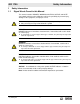
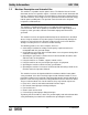
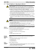
GPi 1700 1 1.1 Safety Information Safety Information Signal Words Found in this Manual This manual contains DANGER, WARNING, CAUTION, NOTICE, and NOTE signal words which must be followed to reduce the possibility of personal injury, damage to the equipment, or improper service. This is the safety alert symbol. It is used to alert you to potential personal hazards. f Obey all safety messages that follow this symbol.
Safety Information 1.2 GPi 1700 Machine Description and Intended Use This machine is a portable electric power source. The Wacker Neuson Inverter Generator consists of a gasoline engine, a fuel tank, and an electric alternator and inverter. Controls and receptacles are provided on a control panel mounted on the side of the machine. As the engine runs, the generator converts mechanical energy into AC power and DC power. The operator connects loads to the AC power receptacles or DC terminals.
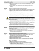
GPi 1700 1.3 Safety Information Safety Guidelines for Operating the Machine DANGER Carbon monoxide. Using a generator indoors CAN KILL YOU IN MINUTES. Generator exhaust contains carbon monoxide (CO). This is a poison you cannot see or smell. If you can smell the generator exhaust, you are breathing CO. But even if you cannot smell the exhaust, you could be breathing CO. f NEVER use a generator inside homes, garages, crawlspaces, or other partly enclosed areas.
Safety Information Electrical safety GPi 1700 Make sure the machine is on a firm, level surface and will not tip, roll, slide, or fall while operating. Remove all tools, cords, and other loose items from the generator before starting it. To increase electrical safety while operating this machine: Do not operate the generator, or tools attached to the generator, with wet hands. Do not use worn electrical cords. Severe electrical shock and equipment damage may result.
GPi 1700 Safety Information overhead is clear of debris that could fall onto or into the machine or exhaust compartment. Storing the machine 1.4 Store the machine properly when it is not being used. The machine should be stored in a clean, dry location out of the reach of children. Operator Safety While Using Internal Combustion Engines WARNING Internal combustion engines present special hazards during operation and fueling.
Safety Information 1.5 GPi 1700 Guidelines for Service Safety WARNING A poorly maintained machine can be a personal injury hazard. f Follow the Periodic Maintenance schedule in this Operator’s Manual. f Repair or replace any damaged or defective components immediately.
GPi 1700 1.6 Safety Information Label Locations C A D E H F G B wc_gr006811 wc_si000347gb.
Safety Information 1.7 GPi 1700 Machine Labels Wacker Neuson machines use international pictorial labels where needed. These labels are described below. Ref. Label Definition A DANGER Using a generator indoors CAN KILL YOU IN MINUTES. Generator exhaust contains carbon monoxide. This is a poison you cannot see or smell. NEVER use inside a home or garage, EVEN IF doors and windows are open. Only use OUTSIDE and far away from windows, doors, and vents. B Oil fill location 14 wc_si000347gb.
GPi 1700 Safety Information Ref. wc_si000347gb.fm Label Definition C WARNING To reduce the risk of injury, user must read and understand instruction manual. Exhaust gas contains poisonous carbon monoxide. Do not use in poorly ventilated area. The operator may suffer severe elecrtric shock. Do not touch with wet hands. The operator may suffer burns. Do not touch hot muffler. Potential danger of explosion or fire. Stop engine during fuel supply. Keep flammable things away.
Safety Information Ref. GPi 1700 Label Definition G WARNING Hot surface! Do not touch. DANGER Risk of carbon monoxide poisoning. Keep a safe distance away from the machine. H WARNING Hot surface! Do not touch. 16 wc_si000347gb.
GPi 1700 2 Operation Operation DANGER Carbon monoxide. Using a generator indoors CAN KILL YOU IN MINUTES. Generator exhaust contains carbon monoxide (CO). This is a poison you cannot see or smell. If you can smell the generator exhaust, you are breathing CO. But even if you cannot smell the exhaust, you could be breathing CO. f NEVER use a generator inside homes, garages, crawlspaces, or other partly enclosed areas. Deadly levels of carbon monoxide can build up in these areas.
Operation 2.3 GPi 1700 Features and Components l a b d e c f n g o l k h m j i wc_gr006650 18 wc_tx001234gb.
GPi 1700 2.4 Operation Ref. Description Ref. Description a Recoil starter i OIl drain plug b Control panel j Right side panel c Left side panel k Oil filler / oil gauge d Air cleaner l Spark plug cap e Fuel drain screw m Spark arrester f Carrying handle n Fuel filter g Fuel tank cap cover o Rear cover h Exhaust outlet — — Lifting and Transporting Lifting and carrying the machine This generator is designed be lifted and carried by one person.
Operation 2.6 GPi 1700 Power Requirements Application This generator is designed to operate single-phase, 60 Hz equipment running at 120 VAC. It also provides DC power strictly intended for charging 12V automotive style batteries. Check the nameplate or label provided on tools and equipment to make sure their power requirements are met by the power output of the generator. If the wattage is not given for a particular tool or piece of equipment, contact the tool manufacturer for wattage requirements.
GPi 1700 2.7 Operation Use of Extension Cords When a long extension cord is used to connect an appliance or tool to the generator, a voltage loss occurs—the longer the cord, the greater the voltage loss. This results in less voltage being supplied to the appliance or tool and increases the amount of current draw or reduces performance. A heavier cord with a larger wire size will reduce the voltage loss. WARNING Electric shock hazard.
Operation 2.8 GPi 1700 Control Panel p q r s t u v CHOKE y w x wc_gr006445 Ref. Description Ref. Description p Pilot indicator light u GFI receptacle (120 VAC) q Overload indicator light v DC terminals r Oil sensor indicator light w DC circuit breaker s Auto power save indicator light x Ground lug t Auto power save switch y Engine switch Pilot indicator light (p) The pilot indicator light illuminates when the generator is operating normally.
GPi 1700 Auto power save indicator light (s) and switch (t) Operation The auto power save indicator light illuminates when the auto power save switch (t) is in positions 1 or 2. With the switch in position 1 (“turtle”), the engine speed automatically adjusts according to the generator load. With the switch in position 2 (“rabbit”), the engine speed remains constant to maintain stable AC power output. This position is ideal for heavy loads. Turn the switch OFF when using DC power.
Operation 2.9 GPi 1700 Customer Connections Description The generator is equipped with : one 120V duplex receptacle (u) with a ground fault circuit interrupt (GFI) one pair of DC terminals (v) exclusively intended for charging 12V automotivestyle batteries. See Using DC Power for more information. u2 u1 u v wc_gr006739 Testing GFI operation The GFI cuts power to the receptacle when a ground fault occurs to a piece of equipment attached to the generator.
GPi 1700 2.10 Operation Grounding the Generator Location The ground lug (x) is located below the DC terminals. x x1 wc_gr006652 Function This ground connection is used for electrically grounding the generator when necessary to comply with the National Electrical Code and other federal, state, and local regulations. For grounding requirements in your area, consult with a qualified electrician, electrical inspector, or local agency having jurisdiction over electrical compliance.
Operation 2.11 GPi 1700 Fueling the Machine Fuel filler cap The fuel filler cap (g1) is located beneath the fuel tank cap cover (g). Turn the fuel filler cap counter-clockwise to open; clockwise to close. g g3 g1 a g2 g v wc_gr006653 WARNING Fire/burn hazards. Gasoline is flammable and can ignite or explode. f Keep all open flames, sparks, and cigarettes away from the machine while refueling. f Do not refuel if the generator is sitting in a truck fitted with a plastic bed liner.
GPi 1700 2.12 Operation Before Starting DANGER Carbon monoxide. Using a generator indoors CAN KILL YOU IN MINUTES. Generator exhaust contains carbon monoxide (CO). This is a poison you cannot see or smell. If you can smell the generator exhaust, you are breathing CO. But even if you cannot smell the exhaust, you could be breathing CO. Explanation Before putting the generator into service, review each item on the following checklist.
Operation 2.13 GPi 1700 Starting the Generator CAUTION Personal injury or machine damage hazards. Starting the generator with equipment attached can damage the generator or the equipment. Unexpected equipment start-up can cause personal injury. f Disconnect all equpment from the generator before starting it. Starting procedure Follow the procedure below to start the machine. 1.
GPi 1700 2.14 Operation Using AC Power Prerequisites Verify that the engine is operating. Verify that pilot indicator light (p) is illuminated. Turn off the equipment to be connected to the generator. Confirm that the equipment to be connected to the generator does not exceed the maximum rated power output and specifed amperage. WARNING Electric shock hazard. Failure to properly ground the generator could lead to electrical sparks, especially if the connected electrical equipment is grounded.
Operation 2.15 GPi 1700 Using DC Power Overview The DC terminals (v) are to be used only for charging 12V batteries. Maximum available power is 12V–8.3A (100W). Both AC and DC output can be used at the same time provided that the total output falls below the maximum rated output of the generator. Prerequisites Verify that pilot indicator light (p) is illuminated. Make sure that the charging cables to be used are rated for 12 V and the maximum CCA rating of the battery.
GPi 1700 Operation Disconnecting When the battery is fully charged: the battery 1. Disconnect the cable from the negative (-) terminals of the battery and the generator. 2. Disconnect the cable from the positive (+) terminals of the battery and the generator. If the DC The DC circuit breaker may activate while a battery is charging.
Maintenance 3 3.1 GPi 1700 Maintenance Periodic Maintenance Schedule The table below lists basic machine and engine maintenance. Tasks designated with check marks may be performed by the operator. Tasks designated with square bullet points require special training and equipment. Refer to the engine owner’s manual for additional information.
GPi 1700 Maintenance When Check engine oil daily before starting the engine, or more than 5 minutes after stopping the engine. Prerequisites Engine is stopped Machine is on a level surface Fresh oil is available (see Technical Data for type and quantity) WARNING Burn hazard. The engine and exhaust pipe become extremely hot during operation. f Stop the engine and allow the machine to cool before checking the engine oil. Procedure Follow the procedure below to check the engine oil level. 1.
Maintenance 3.2 GPi 1700 Cleaning and Checking the Spark Plug When Clean the spark plug and check the electrode gap every 200 hours of operation (monthly). Prerequisite Engine is stopped and cool to the touch WARNING Burn hazard. Engine and exhaust pipe become extremely hot during operation. f Stop the engine and allow the machine to cool before cleaning and adjusting the spark plug. Removing and Follow the procedure below to remove and clean the spark plug. cleaning the 1.
GPi 1700 3.3 Maintenance Cleaning the Air Cleaner Assembly When Clean the air cleaner assembly every 50 hours of operation. Prerequisite Engine is stopped and cool to the touch Description The air cleaner assembly consists of a foam insert housed inside the air cleaner body. Procedure Follow the procedure below to clean the air cleaner assembly. c d1 d wc_gr006659 1. Using a flat screwdriver or a coin, unscrew and remove the left side cover (c) from the generator enclosure. 2.
Maintenance 3.4 GPi 1700 Changing the Engine Oil When Change the engine oil after the first 20 hours of operation, and every 50 hours thereafter. Prerequisites Engine is stopped, but still warm Machine is on a level surface Fresh engine oil (see engine operator’s manual) Plastic cloth and a container of sufficient volume to collect drained oil Note: Collect, store and dispose of drained oil in accordance with current environmental protection regulations. WARNING Burn hazard.
GPi 1700 3.5 Maintenance Cleaning the Spark Arrester When Clean the spark arrester after every 100 hours of operation. Prerequisite Engine is stopped and cool to the touch Description The spark arrester is a cylindrical metal element fastened inside the muffler exhaust port. If the spark arrester is not cleaned regularly, it will become clogged with carbon deposits and impair engine performance. Engine exhaust gases will not flow. Engine output will be reduced. More fuel will be consumed.
Maintenance 3.6 GPi 1700 Cleaning the Fuel Filter When Clean the fuel filter monthly, or after every 200 hours of operation. Prerequisite Engine is stopped and cool to the touch Description The fuel filter (g2) is located beneath the fuel tank cap (g1). The fuel filter screen removes sediment and other impurities from fuel added to the tank. Procedure Follow the procedure below to clean the fuel filter. g1 g2 g3 g wc_gr006744 1. Lift the fuel tank cap cover (g).
GPi 1700 3.7 Maintenance Storing the Generator When Follow the procedures described below if you intend to take your generator out of service and store it for at least six months. Tasks The following tasks must be performed in order to prepare the generator for storage: 1. Drain fuel from the fuel tank. 2. Drain fuel from the carburetor. 3. Change the engine oil. 4. Check for loose or missing fasteners; tighten or replace as needed. 5. Clean generator body. 6. Store the generator.
Maintenance Draining the carburetor GPi 1700 3. Re-install the fuel tank cap, and close the fuel tank cap cover. 4. Place a plastic cloth and a collection container beneath the machine. 5. Using a flat screwdriver or a coin, unscrew and remove the left side cover (c) from the generator enclosure. e c e wc_gr006661 6. Locate and remove the fuel drain screw (e). Fuel will drain from the attached plastic tube. 7. Collect and dispose of drained fuel. 8. Re-install the fuel drain screw. 9.
GPi 1700 Maintenance Notes: wc_tx001235gb.
Schematic 4 GPi 1700 Schematic A B J C Q D P K E F O N L G M H R wc_gr006649 42 wc_tx001236gb.
GPi 1700 4.1 Schematic Schematic Components Component Component A Engine K Inverter and engine control unit B Control panel L DC circuit breaker C Step motor M DC output terminal D Ignition coil N Ground terminal E Pickup coil O Engine switch F Oil level sensor P Auto power save switch G Main coil Q AC receptacle H DC coil R Generator J LED indicator Wire Colors wc_tx001236gb.
Basic Troubleshooting 5 GPi 1700 Basic Troubleshooting Problem Cause Remedy Engine is difficult to start 1. Fuel is contaminated 1. Clean fuel filter and fuel tank. Remove water, dirt, and other impurities. 2. Spark plug gap setting is incorrect 2. Check and adjust spark plug gap clearance if necessary. Engine does not start 1. Engine switch in wrong position 1. Turn engine switch to CHOKE position. 2. No fuel 2. Refill fuel tank. 3. Equipment is connected to the generator 3.
GPi 1700 6 6.1 Technical Data Technical Data Engine Engine Power Rating Net power rating per SAE J1349. Actual power output may vary due to conditions of specific use. Model GPi 1700 Engine Engine make Robin Engine model EH09-2 Number of cylinders 1 Displacement cm³ (in³) 85.8 (5.23) Engine speed rpm 3000–4200 Max. rated power @ rated speed kW (hp) 2.1 (2.82) @ 4200 rpm type NGK BM6A or BMR6A mm (in.) 0.7–0.8 (0.028–0.
Technical Data 6.2 GPi 1700 Generator Data Machine GPi 1700 Machine Generator type Generator speed Multi-pole revolving field inverter rpm 3000–4200 Rated AC voltage V 120 Rated frequency Hz 60 Rated AC current A 11.3 KVA 1.35 Rated AC output Rated power factor 1.0 Rated DC voltage V 12 Rated DC current A 8.
Engine Emission Warranty Information and Statement
R1700I(US)_GU2093 05.3.8 1:46 PM ページ01 WARNING : The engine exhaust from this product contains chemicals known to the State of California to cause cancer, birth defects or other reproductive harm. NOTICE NOTICE To the engines/generators exported to and used in the countries other than the U.S.A., warranty service shall be performed by the distributor in each country in accordance with the standard Robin engine/generator warranty policy as applicable.
R1700I(US)_GU2093 05.3.8 1:46 PM ページ02 FEDERAL EMISSIONS COMPONENT DEFECT WARRANTY EMISSIONS COMPONENT DEFECT WARRANTY COVERAGE – This emission warranty is applicable in all States, except the state of California. Fuji Heavy Industries Ltd. and Robin America Inc.
R1700I(US)_GU2093 05.3.8 1:46 PM ページ03 CALIFORNIA EMISSION CONTROL WARRANTY STATEMENT YOUR WARRANTY RIGHTS AND OBLIGATIONS The California Air Resources Board and Fuji Heavy Industries Ltd. (herein “FUJI”) are pleased to explain the emission control system warranty on your 2005 and later Small Off-Road engine (herein "engine"). In California, new engine must be designed, built and equipped to meet the State's stringent anti-smog standards.
R1700I(US)_GU2093 05.3.8 1:46 PM ページ04 When warranty repair is needed, the engine must be brought to an authorized service dealer or warranty station’s place of business during normal business hours. In all cases, a reasonable time, not to exceed 30 days, must be allowed for the warranty repair to be completed after the engine is received by the authorized service dealer or warranty station. G.
R1700I(US)_GU2093 05.3.8 1:46 PM ページ12 ENGLISH MAINTENANCE SCHEDULE MAINTENANCE, REPLACEMENT OR REPAIR OF THE EMISSION CONTROL DEVICES AND SYSTEMS MAY BE PERFORMED BY ANY NONROAD ENGINE REPAIR ESTABLISHMENT OR INDIVIDUAL.
Wacker Neuson SE · Preußenstraße 41 · D-80809 München · Tel.: +49-(0)89-3 54 02-0 · Fax: +49 - (0)89-3 54 02-390 Wacker Neuson Corporation · N92W15000 Anthony Ave. · Menomonee Falls, WI 53051 · Tel. : (262) 255-0500 · Fax: (262) 255-0550 ·Tel. : (800) 770-0957 Wacker Neuson Limited - Room 1701–03 & 1717–20, 17/F. Tower 1, Grand Century Place, 193 Prince Edward Road West, Mongkok, Kowloon, Hongkong.