
Repair manual

RD 27 Troubleshooting the Drive System
wc_tx000949gb.fm 55
Continued from the previous page.
5. Place the FWD/REV lever in the NEUTRAL position.
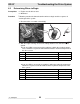
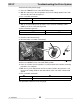
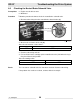
6. With the starter key in the ON position, measure the voltage between wire 307-
OR-16 of the connector and ground.
Is 10.0–12.5 VDC measured?
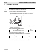
7. With an assistant sitting in the operator’s seat, check the continuity of wire
C906-PU-16 of the connector to ground.
Is there continuity to ground?
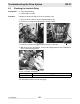
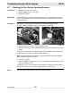
8. Reconnect the interlock relay.
9. Disconnect the seat switch solenoid (c).
10.Place the FWD/REV lever in the NEUTRAL position.
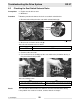
11.Have an assistant sit in the operator’s seat and remain there until the remaining
procedures are complete.
12.With the key in the ON position and an assistant seated in the operator’s seat,
measure the voltage between wire 307-OR-16 of the seat switch solenoid and
ground.
Is 10.0–12.5 VDC measured?
This procedure continues on the next page.
Yes ____ No ____
Continue. Repair wire 307-OR-16.
Yes ____ No ____
Continue. Check the seat switch.
Yes ____ No ____
Continue. Repair wire 307-OR-16.