Operator’s Manual Pump PST2 400 PSTF2 400 EN 5000188001 5 0 0 0 1 06 8 8 0613 0 0 1
Copyright notice © Copyright 2013 by Wacker Neuson Production Americas LLC All rights, including copying and distribution rights, are reserved. This publication may be photocopied by the original purchaser of the machine. Any other type of reproduction is prohibited without express written permission from Wacker Neuson Production Americas LLC. Any type of reproduction or distribution not authorized by Wacker Neuson Production Americas LLC represents an infringement of valid copyrights.
Foreword Foreword Machines covered in this manual Machine Item Number PST2 400 0009112 PSTF2 400 0620435 This manual provides information and procedures to safely operate and maintain this Wacker Neuson model. For your own safety and protection from injury, carefully read, understand and observe the safety instructions described in this manual. Keep this manual or a copy of it with the machine. If you lose this manual or need an additional copy, please contact Wacker Neuson Corporation.
Foreword wc_tx001173gb.
PST2/PSTF2 400 1. Foreword 3 Safety Information 7 1.1 1.2 2. 9 Names of Parts ..................................................................................... 9 Prior to Operation ............................................................................... 10 Installation .......................................................................................... 10 Installing the Float (if equipped) ......................................................... 13 Electrical Wiring ..............
Table of Contents wc_bo0154618en_005TOC.
PST2/PSTF2 400 1. Safety Information Safety Information This manual contains DANGER, WARNING, CAUTION, NOTICE and NOTE callouts which must be followed to reduce the possibility of personal injury, damage to the equipment, or improper service. This is the safety alert symbol. It is used to alert you to potential personal injury hazards. Obey all safety messages that follow this symbol to avoid possible injury or death.
Safety Information 1.1 PST2/PSTF2 400 Operating and Electrical Safety WARNING 1.2 To reduce risk of electric shock, connect only to a properly grounded, grounding-type receptacle. Risk of electric shock—this pump has not been investigated for use in swimming pool areas. An acceptable motor-control switch shall be provided at the time of installation according to local codes and regulations. To reduce risk of electric shock, follow instructions in this manual for proper installation.
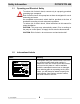
PST2/PSTF2 400 2. Operation Operation 2.1 Names of Parts See Graphic: wc_gr001699 8 1 5 3 2 9 15 10 12 13 6 14 11 wc_gr001699 Ref Description Ref 1 Lifting handle 9 Oil plug 2 Mechanical seal 10 Dust seal 3 Lubricant 11 Sleeve 4 Oil housing 12 Impeller 5 Coupling 13 Stirrer nut 6 Volute 14 Strainer 7 Gasket 15 Oil lifter 8 Cable assembly wc_tx000111gb.
Operation 2.2 PST2/PSTF2 400 Prior to Operation When the pump is delivered, first perform the following checks: • Inspection While unpacking, inspect the product for damage during shipment, and make sure all bolts and nuts are tightened properly. • Specification check Check the model number to make sure it is the product that was ordered. Be certain it is the correct voltage and frequency.
PST2/PSTF2 400 Operation Preparing for installation Before installing the pump at a work site, you will need to have the following tools and instruments ready: • Insulation resistance tester (megohmmeter) • AC voltmeter • AC ammeter (clamp-on type) • Bolt and nut tighteners • Power supply connection tools (screwdriver or box wrench) Note: Please also read the instructions that come with each of the test instruments.
Operation 2.3.2 PST2/PSTF2 400 Install the pump in a location with sufficient water level, where water collects readily. Note: See Operation (“Operating Water Level”) for the water level necessary for operation. Note: The discharge end of the hose should be located higher than the water surface. If the end of the hose is submerged, water may flow back to the pump when the pump is stopped; and if the hose end is lower than the water surface, water may overflow when the pump is turned off.
PST2/PSTF2 400 2.4 Operation Installing the Float (if equipped) See graphic: wc_gr005664 wc_gr005664 2.4.1 Set the length of the float lead wire to the dimension indicated below. Failure to set the correct lead wire length will lead to improper operation of the pump. Pump model Length “L” PSTF2 400 150 mm (5.9 in.) NOTICE: Install the float so that it moves freely up and down. If the float binds or catches, it will cause the pump to operate improperly. wc_tx000111gb.
Operation PST2/PSTF2 400 Notes: wc_tx000111gb.
PST2/PSTF2 400 2.5 Operation Electrical Wiring WARNING Performing electrical wiring Electrical wiring should be performed by a qualified person in accord with all applicable regulations. Failure to observe this precaution not only risks breaking the law but is extremely dangerous. Incorrect wiring can lead to current leakage, electrical shock or fire.
Operation PST2/PSTF2 400 See Graphic: wc_gr000242 CAUTION wc_tx000111gb.fm Cable Assembly If it is necessary to extend the cable assembly, use a core size equal to or larger than the original. This is necessary not only to avoid a performance drop, but to prevent cable overheating which can result in fire, electrical leakage or electrical shock.
PST2/PSTF2 400 2.6 Operation Electrical Circuit Diagrams See Graphic: wc_gr006190 PST2 400 R 1 R L W B W 3 2 5 G G/Y 6 4 8 PSTF2 400 R(Br) R 1 L L B W (L) 6 2 W 5 3 4 Y/G wc_gr006190 If connected to a circuit protected by a fuse, use a time-delay fuse with this pump. CAUTION Ref. Description Ref. Description 1 Capacitor 5 Frame grounding 2 Main coil 6 Ground 3 Auxiliary coil 8 Float switch (normally open contact) 4 Miniature protector wc_tx000111gb.
Operation PST2/PSTF2 400 Wire Colors wc_tx000111gb.
PST2/PSTF2 400 2.7 Operation Operation Before starting 2.7.1 Make sure once again that the product is of the correct voltage and frequency rating. NOTICE: Using the product at other than rated voltage and frequency will not only lower its performance but may damage the product. Note: Confirm the rated voltage and frequency on the model nameplate. 2.7.2 Confirm the wiring, supply voltage, circuit breaker capacity, and motor insulation resistance. Reference insulation resistance = 20 MW or greater.
Operation CAUTION WARNING CAUTION wc_tx000111gb.fm PST2/PSTF2 400 COUNTERMEASURE: If the supply voltage is outside the tolerance, possible causes are the power supply capacity or an inadequate extension cable. Look again at the wiring diagram and make sure the conditions are proper. In case of very excessive vibration, unusual noise or odor, turn off the power immediately and consult your nearest dealer or Wacker representative.
PST2/PSTF2 400 CAUTION Operation Operating water level Do not operate the pump below the C.W.L. (Continuous running Water Level) indicated below. Failure to observe this condition may result in damage to the pump, current leakage or electrical shock. See Graphic: wc_gr001222 C.W.L wc_gr001222 NPT 45-degree hose coupling is standard for the US market. Pump Model Continuous running Water Level PST2 400 w/strainer 90mm (3.5") PST2 400 w/residue plate 10mm (0.4”) PSTF2 400 120mm (4.
Operation 2.8 PST2/PSTF2 400 Automatic Operation (PSTF2 400 only) See Graphic: wc_gr005666 The PSTF2 400 pump is equipped with a float switch to detect the water level. The float switch (a) enables the pump to perform an automatic drainage operation when connected to a continuous power supply. a wc_gr005666 Connect the power and perform a trial operation as follows: 2.8.1 Move the float switch down to its lowest position. 2.8.2 Raise the float switch. This will start the pump. 2.8.
PST2/PSTF2 400 2.9 Operation Residue Plate See graphic: wc_gr001144 The residue plate kit contains the residue plate, washers, and bolts. Reuse nuts from pump assembly. 2.9.1 Remove the strainer (3) by loosening the three nuts (1) and removing the three bolts (2). Keep nuts for reuse. 2.9.2 Position washers (4) and attach the residue plate (5) with new bolts (6) included with kit. Note: Be certain to use washers to prevent motor shaft stirrer nut from protruding through residue plate.
Maintenance 3. PST2/PSTF2 400 Maintenance 3.1 Periodic Maintenance Table Pump Weekly Measure insulation resistance. Reference insulation resistance = 1MW or greater. (1) ■ Measure operating current. Compare with rated current. ■ Measure supply voltage. Compare with allowable range (within ±5% of rated voltage). ■ Pump inspection. A noticeable drop in performance may indicate wear in the impeller, etc., or else clogging of the strainer, etc. Remove the clogged debris and replace any worn parts.
PST2/PSTF2 400 3.2 Maintenance Maintenance and Inspection WARNING 3.2.1 Regular maintenance and inspections are a necessity for continued efficient functioning of the pump. If any abnormal conditions are noticed, refer to the Troubleshooting section and take corrective measures immediately. It is recommended that a spare pump be kept ready in case of any problems. Prior to inspecting Before inspecting the pump, make certain the power supply (circuit breaker, etc.) is turned off.
Maintenance PST2/PSTF2 400 See Graphic: wc_gr000245 Ref. Description Ref. Description 1 Oil inlet 3 Oil plug 2 Gasket 4 Allen wrench Pump Model Lubricant Capacity PST2 400 PSTF2 400 160 ml (5.4 fl. oz.) Replacement Parts The table lists the parts that need to be replaced periodically. Replace these using the recommended frequency as a guideline. Part Replacement Frequency Mechanical seal When lubricant in oil compartment becomes milky.
PST2/PSTF2 400 3.3 Maintenance Disassembly and Reassembly WARNING Before disassembling the pump, make certain the power supply (circuit breaker, etc.) is turned off. Then, unplug the cable assembly from the receptacle or detach it from the terminals. To avoid electrical shock, DO NOT work with wet hands. NEVER check the operation of any parts (impeller rotation, etc.) by turning on the power while the unit is partially assembled. Failure to observe these precautions may result in a serious accident.
Maintenance 3.4 PST2/PSTF2 400 Disassembly See Graphic: wc_gr000411 Note: For assembly or disassembly, place the pump on its side. Note: It is not necessary to drain the oil for disassembly and inspect ion of the impeller (w) or volute (aa). However, drain oil if further disassembly and testing is required. 3.4.1 Remove three nuts (af) and the suction strainer (ac). 3.4.2 Remove volute (aa) and volute gasket (ah). 3.4.
PST2/PSTF2 400 3.5 Maintenance Impeller Inspection See Graphic: wc_gr000411 3.5.1 Visually inspect impeller (w) for corrosion, wear or damage. Worn impellers compromise peak performance. 3.5.2 Visually inspect impeller key and rotor shaft keyway for signs of uneven wear. 3.5.3 Visually inspect volute (aa) casting for cracks, wear and damage. Look for signs of wear on volute cutwaters and surfaces facing impeller. wc_tx000112_orig_gb.
Maintenance 3.6 PST2/PSTF2 400 Impeller Reassembly See Graphic: wc_gr000411 Note: If, upon inspection and testing, a pump component requires replacement, use only original manufacturer’s replacement parts. 3.6.1 Turn pump on its side. 3.6.2 Pre-assemble the dust seal (u) and sleeve (v). Slide the two pieces (u & v) onto the rotor shaft. DO NOT apply oil to the surface where the dust seal (u) contacts the sleeve (v). 3.6.
PST2/PSTF2 400 3.7 Maintenance Troubleshooting Before ordering repairs, carefully read through this manual, then repeat the inspection. If the problem remains, contact your nearest dealer or Wacker Neuson representative. Always turn off the power before inspecting the pump. Failure to observe this precaution can result in serious accident.
Technical Data 4. PST2/PSTF2 400 Technical Data 4.
PST2/PSTF2 400 4.2 Technical Data Operating Specifications Part No. PST2 400 / PSTF2 400 Pump Electric Power V/Ph/Hz Rated Current A 110/1/60 5.4 Starting Method Capacitor-Run Bore mm (in.) 50 (2) Output kW (Hp) 0.40 (0.50) Maximum Head m (ft.) 12 (39) Maximum Capacity L/min (GPM) 200 (53) Maximum Pressure psi Solid Size Capacity mm (in.) 9.5 (0.4) Weight* Kg (lbs.) 11.3 (25) 16.
Technical Data 4.3 PST2/PSTF2 400 Dimensions 4.3.1 340*** (13.5) 185 (7.3) 250 (9.8) 185 (7.3) 255 (10.1) 207 (8.1) 90* (3.5) 328 (12.9) 385**** 40** (15.2) (1.6) 2" 45° 330 (13.0) 162 (6.4) 120*** (4.8) 84 (3.3) PSTF2 400 PST2 400 wc_gr006191 *Start range ** Stop range *** Minimum **** Maximum wc_td000034gb.
Important: For spare parts information, please see your Wacker Neuson Dealer, or visit the Wacker Neuson website at http://www.wackerneuson.com/. Wichtig! Informationen über Ersatzteile erhalten Sie von Ihrem Wacker Neuson Händler oder besuchen Sie die Wacker Neuson Website unter http://www.wackerneuson.com/. Important : Pour des informations sur les pièces détachées, merci de consulter votre distributeur Wacker Neuson, ou de visiter le site Internet de Wacker Neuson sur http://www.wackerneuson.com/.