Operator’s Manual Vibroplate WP 1550 WP 1550W 5000190507 5 0 0 0 1 12 9 0 0811 5 0 7
Copyright notice © Copyright 2011 by Wacker Neuson Corporation. All rights, including copying and distribution rights, are reserved. This publication may be photocopied by the original purchaser of the machine. Any other type of reproduction is prohibited without express written permission from Wacker Neuson Corporation. Any type of reproduction or distribution not authorized by Wacker Neuson Corporation represents an infringement of valid copyrights. Violators will be prosecuted.
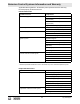
WP 1550 Table of Contents Foreword 3 1. Emission System Control Information 4 2. Safety Information 9 3. 4. 2.1 Laws Pertaining to Spark Arresters .................................................... 10 2.2 Operating Safety ................................................................................ 11 2.3 Operator Safety while using Internal Combustion Engines ................ 12 2.4 Service Safety ....................................................................................
Table of Contents 5. WP 1550 Maintenance 5.1 5.2 5.3 5.4 5.5 5.6 5.7 5.8 5.9 5.10 5.11 5.12 5.13 29 Maintaining the Emission Control System............................................29 Periodic Maintenance Schedule ..........................................................29 Cleaning Plate .....................................................................................31 Drive Belt .............................................................................................31 Exciter Lubrication .
WARNING CALIFORNIA Proposition 65 Warning: Engine exhaust, some of its constituents, and certain vehicle components, contain or emit chemicals known to the State of California to cause cancer and birth defects or other reproductive harm. Foreword This manual provides information and procedures to safely operate and maintain this Wacker Neuson model. For your own safety and protection from injury, carefully read, understand and observe the safety instructions described in this manual.
Emission Control Systems Information and Warranty 1 Emission Control Systems Information and Warranty The Emission Control Warranty and associated information is valid only for the U.S.A., its territories, and Canada. 1.1 Emission Control System Background Information Introduction Wacker Neuson spark-ignited engines/equipment must conform with applicable Environmental Protection Agency (EPA) and the State of California emissions regulations.
Emission Control Systems Information and Warranty Tampering and Altering Tampering with or altering the emission control system may increase emissions beyond the legal limit. If evidence of tampering is found, Wacker Neuson may deny a warranty claim. Among those acts that constitute tampering are: Removing or altering of any part of the air intake, fuel, or exhaust systems. Altering or defeating the speed-adjusting mechanism causing the engine to operate outside its design parameters. 1.
Emission Control Systems Information and Warranty applicable EPA regulations. All defective parts replaced under this warranty become property of Wacker Neuson.
Emission Control Systems Information and Warranty What is not covered Failures other than those resulting from defects in material or workmanship. Any systems or parts which are affected or damaged by owner abuse, tampering, neglect, improper maintenance, misuse, improper fueling, improper storage, accident and/or collision; the incorporation of, or any use of, add-on or modified parts, or unsuitable attachments, or the alteration of any part.
Emission Control Systems Information and Warranty For owners located more than 100 miles from an authorized dealer/service center (excluding the states with high-altitude areas as identified in 40 CFR Part 1068, Appendix III), Wacker Neuson will pay for pre-approved shipping costs to and from an authorized Wacker Neuson dealer/service center.
WP 1550 2. Safety Information Safety Information This manual contains DANGER, WARNING, CAUTION, NOTICE, and NOTE signal words which must be followed to reduce the possibility of personal injury, damage to the equipment, or improper service. This is the safety alert symbol. It is used to alert you to potential personal injury hazards. Obey all safety messages that follow this symbol to avoid possible injury or death.
Safety Information 2.1 WP 1550 Laws Pertaining to Spark Arresters Notice: State Health Safety Codes and Public Resources Codes specify that in certain locations spark arresters be used on internal combustion engines that use hydrocarbon fuels. A spark arrester is a device designed to prevent accidental discharge of sparks or flames from the engine exhaust. Spark arresters are qualified and rated by the United States Forest Service for this purpose.
WP 1550 2.2 Safety Information Operating Safety WARNING Familiarity and proper training are required for the safe operation of the machine. Machines operated improperly or by untrained personnel can be hazardous. Read the operating instructions contained in this manual and the engine manual, and familiarize yourself with the location and proper use of all controls. Inexperienced operators should receive instruction from someone familiar with the machine before being allowed to operate it. 2.2.
Safety Information 2.3 WP 1550 Operator Safety while using Internal Combustion Engines WARNING Internal combustion engines present special hazards during operation and fueling. Read and follow the warning instructions in the engine owner’s manual and the safety guidelines below. Failure to follow the warnings and safety standards could result in severe injury or death. 2.3.
WP 1550 2.4 Safety Information Service Safety A poorly maintained machine can become a safety hazard! In order for the machine to operate safely and properly over a long period of time, periodic maintenance and occasional repairs are necessary. WARNING 2.4.1 Do not attempt to clean or service the machine while it is running. Rotating parts can cause severe injury. 2.4.2 Do not crank a flooded engine with the spark plug removed on gasoline-powered engines.
Safety Information 2.5 WP 1550 Label Locations wpmgr005959 WARNING WARNUNG ADVERTENCIA AVERTISSEMENT 1 wpm_si000324gb.
WP 1550 2.6 Safety Information Warning and Informational Labels Wacker Neuson machines use international pictorial labels where needed. These labels are described below. Label Meaning WARNING! To prevent hearing loss, wear hearing protection when operating the machine. Read the Operator’s Manual for machine information. Check engine oil level. Use SAE10W30. 9 ! Check the fuel level. WARNING! Hot surface! Guaranteed sound power level in dB(A). wpm_si000324gb.
Safety Information Label WP 1550 Meaning WARNING! Hand injury if caught in moving belt. Always replace beltguard. CAUTION! Read and understand the supplied Operator’s Manual before operating this machine. Failure to do so increases the risk of injury to yourself and others. NOTICE Lifting point. Lifting point (manual). DANGER! Engines emit carbon monoxide; operate only in well-ventilated area. Read the Operator’s Manual. No sparks, flames, or burning objects near the machine.
WP 1550 Label Safety Information Meaning Company logo A nameplate listing the model number, item number, revision number, and serial number is attached to each unit. Please record the information found on this nameplate so it will be available should the nameplate become lost or damaged. When ordering parts or requesting service information, you will always be asked to specify the model number, item number, revision number, and serial number of the unit. This machine may be covered by one or more patents.
Safety Information 2.7 WP 1550 Operating Labels Wacker Neuson machines use international pictorial labels where needed. These labels are described below. Label Meaning Open the fuel flow valve. Push or turn engine switch to ON position. Close the choke. Place throttle in the IDLE position. Pull the rewind starter. Close the fuel flow valve. wpm_si000324gb.
WP 1550 Safety Information Label Meaning 1 Push or turn engine switch to OFF position. Open the choke. Place throttle in the FAST position. Throttle control lever: Turtle = Idle or Slow Rabbit = Full or Fast wpm_si000324gb.
Technical Data 3. WP 1550 Technical Data 3.1 Engine Data Engine Power Rating Net power rating per SAE J1349. Actual power output may vary due to conditions of specific use. WP 1550, WP 1550 W 0009325, 0009324, 0009548 Engine Engine Make Wacker Engine Model WM170 Max. rated power @ rated speed 4.2 (5.
WP 1550 Technical Data 3.2 Plate Data WP 1550, WP 1550 W 0009325, 0009324, 0009548 Plate Operating Weight Water Tank Capacity Exciter Speed Exciter Lubrication 3.3 88 (194) kg (lbs.) l (qts.) 10.4 (11.0) rpm / belt 5800 ± 100 150 (5) Automatic Transmission Fluid Dextron III / Mercon or equivalent ml (oz.) Sound and Vibration Specifications Products are tested for sound pressure level in accordance with EN ISO 11204.
Technical Data 3.4 WP 1550 Dimensions mm (in.) 38 (965) 34.5 (875) 19.5 (500) wpmgr005986 wpm_td000333gb.
WP 1550 4. Operation Operation 4.1 Recommended Fuel The engine requires regular grade unleaded gasoline. Use only fresh, clean gasoline. Gasoline containing water or dirt will damage fuel system. Consult engine owner’s manual for complete fuel specifications. Use of oxygenated fuels Some conventional gasolines are blended with alcohol. These gasolines are collectively referred to as oxygenated fuels. If you use an oxygenated fuel, be sure it is unleaded and meets the minimum octane rating requirement.
Operation 4.2 WP 1550 Before Starting 4.2.1 Read and understand the safety and operating instructions at the beginning of this manual. 4.2.2 Check: wpm_tx001125gb.
WP 1550 4.3 Operation To Start See Graphic: wc_gr000655 4.3.1 Open fuel valve by moving lever down (a1). Note: If engine is cold, move choke lever to close position (d2). If engine is hot, set choke to open position (d1). 4.3.2 Turn engine switch to “ON” (b2). 4.3.3 Open throttle by moving it slightly to left (c2). 4.3.4 Pull starter rope (e). Note: If the oil level in the engine is low, the engine will not start. If this happens, add oil to engine. 4.3.5 Open choke as engine warms (d1). 4.3.
Operation 4.5 WP 1550 Application This plate is designed for compacting loose, granular soils, gravel, and paving stones. It is intended to be used in confined areas and areas next to structures such as walls, curbs, and foundations. Plates equipped with water tanks can be used for compacting asphalt. This plate is not recommended for compacting cohesive soils with a heavy clay content. For cohesive soil, use a vibratory rammer or sheepsfoot roller. wpm_tx001125gb.
WP 1550 4.6 Operation Operation See Graphic: wpmgr006016 Run engine at full throttle and allow plate to pull itself along at its normal speed. When operating on an incline it may be necessary to assist plate by pushing it forward slightly. Depending on the material being compacted, three or four passes are recommended to achieve the best compaction. While a certain amount of moisture in the soil is necessary, excessive moisture may cause soil particles to stick together and prevent good compaction.
Operation 4.7 WP 1550 Wheel Kit (0162986) See Graphic: wc_gr002793 Wheel kit (Part No. 0162986) is a standard item on Item Number 0009545, 0009546, 0009547 and 0009548 only. Available as an option on all other models. 4.7.1 Disengage wheel kit from holding latch (a) and position wheels in “down” position. 4.7.2 Pivot holding latch and engage cross member brace into latch. NOTICE: Latch prevents vibroplate from pivoting and falling back towards the operator. 4.7.
WP 1550 5. Maintenance Maintenance 5.1 Maintaining the Emission Control System Normal maintenance, replacement or repair of emission control devices and systems may be performed by any repair establishment or individual; however, warranty repairs must be performed by a dealer/service center authorized by WACKER NEUSON.
Maintenance WP 1550 Machine Maintenance The chart below lists basic machine maintenance. Daily before starting Check external hardware. After first 20 hrs. Every 2 weeks or 50 hrs. Every month or 100 hrs. Every year or 300 hrs. Check and adjust drive belt. Inspect shockmounts for damage. Replace shockmounts as needed. Change exciter oil. Note: When machine is being used in asphalt, it is highly recommended that shockmounts are replaced every year or after 300 hours of usage.
WP 1550 5.3 Maintenance Cleaning Plate Clean plate after use to remove dirt, stones, and mud caught under the engine console. If plate is being used in a dusty area, check engine cylinder cooling fins for heavy dirt accumulation. Keep engine cylinder fins clean to prevent engine from overheating. 5.4 Drive Belt See Graphic: wc_gr000077 On new machines or after installing a new belt, check belt tension after first 20 hours of operation. Check and adjust belt every 50 hours thereafter.
Maintenance 5.5 WP 1550 Exciter Lubrication See Graphic: wpmgr006021 The exciter assembly is a self-contained, sealed unit. The bearings are lubricated using automatic transmission fluid (see Technical Data for type). Change fluid once every year or 300 hours of operation. When changing fluid, replace O-ring (a). To change fluid: 5.5.1 Remove beltguard, belt, and hose from water tank. 5.5.2 Remove four screws (b) securing console assembly to baseplate and lift console assembly from baseplate. 5.5.
WP 1550 5.6 Maintenance Spark Plug See Graphic: wc_gr000028 Clean or replace the spark plug as needed to ensure proper operation. Refer to your engine operator’s manual. The muffler becomes very hot during operation and remains hot for a while after stopping the engine. Do not touch the muffler while it is hot. WARNING Note: Refer to section “Technical Data” for the recommended spark plug type and the electrode gap setting. 5.6.1 Remove the spark plug and inspect it. 5.6.
Maintenance 5.7 WP 1550 Engine Oil See Graphic: wc_gr000087 5.7.1 Drain oil while engine is still warm. Note: In the interests of environmental protection, place a plastic sheet and a container under the machine to collect any liquid which drains off. Dispose of this liquid in accordance with environmental protection legislation. 5.7.2 Remove the oil drain plug (a). 5.7.3 Allow the oil to drain. 5.7.4 Install the drain plug. 5.7.
WP 1550 5.8 Maintenance Air Cleaner See Graphic: wc_gr000656 NEVER use gasoline or other types of low-flash point solvents for cleaning the air cleaner. A fire or explosion could result. WARNING NOTICE: NEVER run the engine without the air cleaner. Severe engine damage will occur. The engine is equipped with a dual-element air cleaner. Under normal operating conditions, the elements should be cleaned once every week. Under severe, dry and dusty conditions, the elements should be maintained daily.
Maintenance 5.9 WP 1550 Cleaning the Fuel Strainer 5.9.1 To remove water and dirt, close the fuel lever and remove the fuel strainer. 5.9.2 Inspect the fuel strainer (a) for water and dirt. 5.9.3 After removing any dirt and water, wash the fuel cup with a nonflammable solvent. 5.9.4 Reinstall securely to prevent leakage. wpm_tx001126gb.
WP 1550 Maintenance 5.10 Troubleshooting Problem / Symptom Reason / Remedy Plate does not develop full speed. Poor compaction. • Engine throttle control not completely open. • Throttle control not adjusted correctly. • Ground too wet, plate sticking. Allow soil to dry before compacting. • Drive belt loose or worn, slipping on pulleys. Adjust or replace belt. Check that engine mounting bolts are tight. • Exciter bearings binding. Check condition and level of oil in exciter. Add or change oil.
Maintenance WP 1550 5.12 Lifting Machine See Graphic: wpmgr006037 See Technical Data for the weight of the machine. To lift machine manually: 5.12.1 Stop the engine. 5.12.2 Obtain help from a partner and plan the lift. 5.12.3 Grasp the machine by its cage (a) and lifting slot (b). 5.12.4 Lift the machine as shown. WARNING To reduce risk of back injury while lifting, keep your feet flat on ground and shoulder width apart. Keep your head up and back straight.
WP 1550 Maintenance 5.13 Transporting Machine See Graphic: wpmgr006055 To avoid burns or fire hazards, let engine cool before transporting machine or storing indoors. WARNING 5.13.1 Turn fuel valve to the off position and keep the engine level to prevent fuel from spilling. 5.13.2 Tie down machine on vehicle to prevent machine from sliding or tipping over. Tie machine to vehicle at points shown on graphic. wpmgr006055 wpm_tx001126gb.
EC Declaration of Conformity Manufacturer Wacker Neuson Manila, Inc. Dasmariñas, Cavite, Philippines Product Product WP 1550A, WP 1550AW, WP 1550, WP1550W Product category Vibrating plate Product function Compacting soils Item number 0007579, 0007576, 0009486, 0009325, 0009324, 0009546, 0009548 WP 1550A, WP 1550AW 3.6 kW WP 1550, WP 1550W 4.
Important: For spare parts information, please see your Wacker Neuson Dealer, or visit the Wacker Neuson website at http://www.wackerneuson.com/. Wichtig! Informationen über Ersatzteile erhalten Sie von Ihrem Wacker Neuson Händler oder besuchen Sie die Wacker Neuson Website unter http://www.wackerneuson.com/. Important : Pour des informations sur les pièces détachées, merci de consulter votre distributeur Wacker Neuson, ou de visiter le site Internet de Wacker Neuson sur http://www.wackerneuson.com/.