Technical Reference Hardware Version 10.
XT[2] Series DISK RECORDER - Version 10.04 - Hardware Technical Reference Manual EVS Broadcast Equipment – January 2011 Issue 10.04.A C OPYRIGHT EVS Broadcast Equipment – Copyright © 2002-2011. All rights reserved. D ISCLAIMER The information in this manual is furnished for inform ational use only and subject to change without notice.
Issue 10.04.A XT[2] Series DISK RECORDER – Version 10.04 - Hardware Technical Reference EVS Broadcast Equipment – January 2011 Table of Contents TABLE OF CONTENTS .................................................................................................... II WHAT’S NEW? ................................................................................................................. V 1. OVERVIEW ......................................................................................................
XT[2] Series DISK RECORDER - Version 10.04 - Hardware Technical Reference Manual EVS Broadcast Equipment – January 2011 Issue 10.04.A 2.2 XT[2] 4U BACK PLANE..............................................................................................................23 2.2.1 (XT[2]H-4-A3) Shown with Optional AES on BNC Connector Option....................................23 2.2.2 (XT[2]H-4-A3B) Shown with Optional AES on Multi-pin Connector Option ...........................23 2.3 GPI IN CONNECTIONS ......
Issue 10.04.A 3.4.3 XT[2] Series DISK RECORDER – Version 10.04 - Hardware Technical Reference EVS Broadcast Equipment – January 2011 External RAID Array XT-HDX for XT[2] Server .....................................................................55 Installation and Operation ........................................................................................................................................ 56 Disk Organization ...........................................................................
XT[2] Series DISK RECORDER - Version 10.04 - Hardware Technical Reference Manual EVS Broadcast Equipment – January 2011 Issue 10.04.A What’s New? The following table describes the sections updated to reflect the new and modified features in version 10.04 (compared to version 10.03). In the user manual, the icon has been added on left margin to highlight information on new and updated features. Click the section number (or the description) in the table to jump directly to the corresponding section.
XT[2] Series DISK RECORDER – Version 10.04 - Hardware Technical Reference Manual EVS Broadcast Equipment – January 2011 Issue 10.04.A 1. Overview Welcom e in the EVS range of products and thank you for using an EVS XT[2] server. We will do our best to satisfy your video production needs and we look forward to continuing working with you. The EVS XT[2] series servers are full digital in PAL (625i), NTSC (525i), 720p, 1080i and 1080p standards.
Issue 10.04.A XT[2] Series DISK RECORDER – Version 10.04 - Hardware Technical Reference EVS Broadcast Equipment – January 2011 functions like loop playback, conditional transitions, etc. 1.2 XT[2] PROXY SERVER From Multicam V10.01, a low-resolution option can be set up to use the XT[2] server as a proxy server only. The Proxy servers can be run on large production events as the counterparts of the high-resolution servers.
XT[2] Series DISK RECORDER - Version 10.04 - Hardware Technical Reference Manual Issue 10.04.A EVS Broadcast Equipment – January 2011 The following table specifies the various lengths: Cold swap (without redundant power supply) Description Length (mm) Length (inch.
Issue 10.04.A 1.4.3 XT[2] Series DISK RECORDER – Version 10.04 - Hardware Technical Reference EVS Broadcast Equipment – January 2011 REMOTE CONTROL PANEL Weight: 2.9 Kg / 6.3 Lbs. 1.4.4 10” TOUCH SCREEN VIDEO MONITOR Weight: 3.6 Kg / 7.8 Lbs. 1.4.5 18” TOUCH SCREEN VIDEO MONITOR Weight: 11.0 Kg / 23.9 Lbs. 1.4.6 KEYBOARD Weight: 0.4 Kg / 0.9 Lbs.
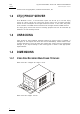
XT[2] Series DISK RECORDER - Version 10.04 - Hardware Technical Reference Manual EVS Broadcast Equipment – January 2011 1.4.7 TABLET Weight: 0.3 Kg / 6.6 Lbs. 1.5 Issue 10.04.A Ref: Wacom® CTF-430 Bamboo One INSTALLATION Before turning on the power, open the front door of Video disk recorder unit to check if all boards fit into their guides. If a board is out of its guides, remove carefully the board and replace it in the same slot. 1.6 SAFETY, COMPLIANCE AND OPERATING CONDITIONS 1.6.
Issue 10.04.A 1.6.3 XT[2] Series DISK RECORDER – Version 10.04 - Hardware Technical Reference EVS Broadcast Equipment – January 2011 EN 55022 European Emission Standard EN 61000-4-3 European European Electromagnetic Compatibility (EMC) Part 4 (Limits), Section 3; Testing and measurem ent techniques - Radiated, radio-Frequency, electromagnetic field immunity test.
XT[2] Series DISK RECORDER - Version 10.04 - Hardware Technical Reference Manual EVS Broadcast Equipment – January 2011 Issue 10.04.A try to correct the interference by one or more of the following measures: 1.6.
Issue 10.04.A XT[2] Series DISK RECORDER – Version 10.04 - Hardware Technical Reference EVS Broadcast Equipment – January 2011 Class of equipment: Class 1 equipment (EN60950 § 1.2.5): electric shock protection by basic insulation and protective earth.
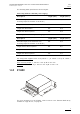
XT[2] Series DISK RECORDER - Version 10.04 - Hardware Technical Reference Manual EVS Broadcast Equipment – January 2011 Issue 10.04.A S ECONDARY P OWER S UPPLY Cold Swap 2 n d Power Supply A 2 n d power supply (cold swap) for the disk recorder unit is available optionally. To connect this 2 n d power supply in case of failure of the main one, remove the metal plate in the top right corner of the back panel, and swap the large electrical connector located inside this compartm ent.
Issue 10.04.A XT[2] Series DISK RECORDER – Version 10.04 - Hardware Technical Reference EVS Broadcast Equipment – January 2011 1.8 XT[2] SERVER MAIN SPECIFICATIONS 1.8.1 VIDEO XT[2] Server Standard Definiti on High Definition Video Formats 525i 59.94fps (NTSC) 625i 60fps (PAL) 720p 50/59.94fps 1080i 50/59.94fps 1080p 50/59.94fps (DualLink) Digital Interface 10-bit 4:2:2 Serial (SMPTE259M). Full frame synchronizer at input. Dual output for PLAY channels. 10-bit 4:2:2 Serial (SMPTE292M).
XT[2] Series DISK RECORDER - Version 10.04 - Hardware Technical Reference Manual EVS Broadcast Equipment – January 2011 Issue 10.04.A Audio Processing 1.8.3 • uncompressed audio • 24 bit processing and storage • sample rate converter from 25-55 kHz to 48KHz • audio scrub • audio mix VIDEO CODECS & BITRATES S UPPORTED C ODECS The EVS XT[2] server uses an intra-frame video encoding technique.
Issue 10.04.A XT[2] Series DISK RECORDER – Version 10.04 - Hardware Technical Reference EVS Broadcast Equipment – January 2011 C ONTENT T RANSFER E NCODING AND F ILE H EADER Up to Multicam 10.01, all codecs used in the EVS Video servers were encoding in 8-bit. From Multicam 10.03, it is possible to perform the encoding process in 8-bit or 10 bit and to write a 10-bit file on selected codecs.
XT[2] Series DISK RECORDER - Version 10.04 - Hardware Technical Reference Manual Issue 10.04.
Issue 10.04.A 1.8.5 XT[2] Series DISK RECORDER – Version 10.04 - Hardware Technical Reference EVS Broadcast Equipment – January 2011 SUPPORTED SMPTE STANDARDS The following standards are supported: 1.8.6 SD SDI SMPTE 259M (525i 59.94Hz; 625i 50Hz) HD SDI SMPTE 292M (720p 50 and 59.94Hz; 1080i 50 and 59.
XT[2] Series DISK RECORDER - Version 10.04 - Hardware Technical Reference Manual Issue 10.04.A EVS Broadcast Equipment – January 2011 2 ch 4 ch 6 ch PAL 185 185 120 NTSC 220 220 145 PAL 50 50 50 NTSC 50 50 50 PAL 100 100 100 NTSC 100 100 100 Apple ProRes 422 DVCPro 50 DVCPro HD 1.8.7 AVID DNXHD ® AND APPLE PRORES 422 I NTRODUCTION EVS XT[2] servers feature a native implementation of the Avid DNxHD® and Apple ProRes 422 high definition video codecs.
Issue 10.04.A XT[2] Series DISK RECORDER – Version 10.04 - Hardware Technical Reference EVS Broadcast Equipment – January 2011 A pple ProRes 422 is also standardized at specific bitrates according to 3 profiles: 1. Apple ProRes 422 (also sometimes referred to as Apple ProRes 422 SQ): 120Mbps in “PAL” (50Hz) and 145Mbps in “NTSC” (59.94Hz) 2. Apple ProRes 422 HQ: 185Mbps in “PAL” (50Hz) and 225Mbps in “NTSC” (59.94Hz) 3. Apple ProRes 422 LT: 85Mbps in “ PAL” (50Hz) and 102Mbps in “NTSC” (59.
XT[2] Series DISK RECORDER - Version 10.04 - Hardware Technical Reference Manual Issue 10.04.A EVS Broadcast Equipment – January 2011 Avid DNxHD® & Apple ProRes 422 at 50Hz (“PAL”) Codec Video Bitrate Fields /Block Actual Bandwidth Max. RT Channels Avid DNxHD® 85 Mbps 100 Mbps 120 Mbps 35 30 11.43 MB/s 13.33 MB/s 13.13 11.25 26 15.38 MB/s 9.75 4.53 9.54 20.31 4.09 8.28 12.46 16.56 185 Mbps 17 23.53 MB/s 6.38 3.11 6.29 13.25 2.43 5.32 8.21 11.
Issue 10.04.A XT[2] Series DISK RECORDER – Version 10.04 - Hardware Technical Reference EVS Broadcast Equipment – January 2011 Avid DNxHD® & Apple ProRes 422 at 180Hz (“NTSC Super Motion 3x”) Codec Video Bitrate Fields /Block Actual Bandwidth Max. RT Channels Avid DNxHD® Avid DNxHD® Avid DNxHD® Apple ProRes 422 Avid DNxHD® Apple ProRes 422 HQ 85 Mbps 100 Mbps 145 Mbps 15 12 9 31.97 MB/s 39.96 MB/s 53.28 MB/s 4.69 3.75 2.82 220 Mbps 6 79.92 MB/s 1.
XT[2] Series DISK RECORDER - Version 10.04 - Hardware Technical Reference Manual EVS Broadcast Equipment – January 2011 Issue 10.04.A Gigabit Ethernet Transfers with XT[2] Servers for Avid DNXHD® and Apple ProRes 422 Preliminary note The following observations focus on steady rates; the transfer performances with small clips will be lower as they generate a lot of starts and ends of sessions.
Issue 10.04.A XT[2] Series DISK RECORDER – Version 10.04 - Hardware Technical Reference EVS Broadcast Equipment – January 2011 I MPORTANT R ECOMMENDATIONS 1.8.8 • For 6-channel configuration, m aximum bitrates for Avid DN xHD® or Apple ProRes 422 should be 220Mbps (NTSC) or 185Mbps (PAL). • “Super Motion + 1 Cam” configuration (i.e. 1 Super Motion REC + 1 Std REC + 1 Super Motion PLAY + 1 Std PLAY): maximum bitrates for Avid DNxHD® or Apple ProRes 422 should be 145Mbps (NTSC) or 185Mbps (PAL).
XT[2] Series DISK RECORDER - Version 10.04 - Hardware Technical Reference Manual EVS Broadcast Equipment – January 2011 Issue 10.04.A can be enabled or disabled by the operator on all EVS slow motion systems. 2- LINE I NTERPOLATOR The 2-line interpolator actually generates a new field, when the original field is in parity violation. Each line of this new field is calculated by a weighted average of the 2 neighbouring lines.
Issue 10.04.A XT[2] Series DISK RECORDER – Version 10.04 - Hardware Technical Reference EVS Broadcast Equipment – January 2011 2. Cabling 2.
XT[2] Series DISK RECORDER - Version 10.04 - Hardware Technical Reference Manual EVS Broadcast Equipment – January 2011 Issue 10.04.A 2.2 XT[2] 4U BACK PLANE 2.2.1 (XT[2]H-4-A3) SHOWN WITH OPTIONAL AES ON BNC CONNECTOR OPTION 2.2.
Issue 10.04.A 2.3 XT[2] Series DISK RECORDER – Version 10.04 - Hardware Technical Reference EVS Broadcast Equipment – January 2011 GPI IN CONNECTIONS On XT servers, GPI triggers are available from Multicam version 5.03.25 or higher. Refer to the Multicam or AirBox user manuals for GPI allocation. IN + GPI 1 IN + GPI 2 IN + GPI 3 IN + GPI 4 RELAY Æ OPTO INPUTS ON THE XT SERVER (GPI INPUTS 1, 2, 3, 4) V+ 2.3.
XT[2] Series DISK RECORDER - Version 10.04 - Hardware Technical Reference Manual Issue 10.04.A EVS Broadcast Equipment – January 2011 IN + GPI 84 IN + GPI 73 TTL 1 TTL 2 TTL 3 TTL 4 Common Ground IN + GPI 62 TTL Æ TTL INPUTS ON THE XT SERVER (GPI INPUT 5, 6, 7, 8) IN + GPI 51 2.3.3 13 12 11 10 9 8 7 6 5 4 3 2 1 Ground 25 24 23 22 21 20 19 18 17 16 15 14 Each TTL input on the DB25 is directly connected to the pin of the TTL connector on the device triggering the GPI.
Issue 10.04.A XT[2] Series DISK RECORDER – Version 10.04 - Hardware Technical Reference EVS Broadcast Equipment – January 2011 2.5 MTPC GPIO CONNECTOR 15/10/02 2.5.1 GPIO CONNECTOR: SUB-D 25-PINS MALE 2.5.
XT[2] Series DISK RECORDER - Version 10.04 - Hardware Technical Reference Manual EVS Broadcast Equipment – January 2011 • o i=2.5 to 30 m A -> opto ON o imax= 30 mA Issue 10.04.A Direct connection to a TTL/CMOS signal possible (Pin opto - to GND and pin opto + to the TTL/CMOS signal. Typical switching point @ 1.6 Volts, for secure operation: o Vin< 0.8 Volts -> opto OFF o Vin> 2.2 Volts @ 2 mA -> opto ON o Vin max (without external resistor) = 15 Volts 4 X CMOS Input/Output: 2.
Issue 10.04.A XT[2] Series DISK RECORDER – Version 10.04 - Hardware Technical Reference EVS Broadcast Equipment – January 2011 2.7 AUDIO CONFIGURATIONS 2.7.1 CODA FOR XT[2] Internal Audio Module: Em bedded + AES/EBU + Analogue Balanced 2.7.
XT[2] Series DISK RECORDER - Version 10.04 - Hardware Technical Reference Manual Issue 10.04.A EVS Broadcast Equipment – January 2011 Analogue DB15 Connectors Pin # 1 2 3 4 5 6 7 8 9 10 11 12 13 14 15 2.
Issue 10.04.A 2.8.1 30 XT[2] Series DISK RECORDER – Version 10.
XT[2] Series DISK RECORDER - Version 10.04 - Hardware Technical Reference Manual EVS Broadcast Equipment – January 2011 2.8.2 Issue 10.04.
Issue 10.04.A 2.8.3 XT[2] Series DISK RECORDER – Version 10.04 - Hardware Technical Reference EVS Broadcast Equipment – January 2011 REQUIRED CONDITIONS TO SET UP AND RUN XNET 1. All systems on the netw ork must be XT[2], XT[2]+, XS, XF[2], XStore[2] or XHub[2]. 2. The SDTI advanced option code (for network client, master or server modes) must be validated in the options list. 3. They should all be running compatible software version.
XT[2] Series DISK RECORDER - Version 10.04 - Hardware Technical Reference Manual EVS Broadcast Equipment – January 2011 Cable type @ 1485 Mbps @ 540 Mbps RG59 45m / 148ft 100m / 328ft RG6 90m / 484ft 180m / 590ft RG11 120m / 393ft 250m / 820ft Super HiQ 150m / 492ft 350m / 1148ft Fiber 80km(*) 200km(*) Issue 10.04.A (*) 80km/200km is the total length of the return path, i.e. the actual distances between the 2 servers connected via the fiber link is half of this value, i.e.
Issue 10.04.A 2.8.5 XT[2] Series DISK RECORDER – Version 10.04 - Hardware Technical Reference EVS Broadcast Equipment – January 2011 XNET PERFORMANCES & TROUBLESHOOTING 1. With the default settings, 10 real-time transfers can be achieved on the network with standard definition pictures in normal conditions, and 3 real-time transfers with super motion pictures. Copy of a clip between 2 servers on the network can be made up to 5 times faster than real time, depending on network load.
XT[2] Series DISK RECORDER - Version 10.04 - Hardware Technical Reference Manual EVS Broadcast Equipment – January 2011 2.9 GIGABIT NETWORK 2.9.1 FUNCTIONAL OVERVIEW Issue 10.04.A The Gigabit connection makes it possible to transfer video and audio material from the XT servers to external systems via the TCP/IP network. The external systems can be the following: • A storage system or an archiving system, such as XStore or XF[2].
Issue 10.04.A 2.9.2 XT[2] Series DISK RECORDER – Version 10.04 - Hardware Technical Reference EVS Broadcast Equipment – January 2011 BACKUP OF CLIPS The following schema shows how the backup of clips is performed with the Gigabit connection and XTAccess: Workflow 1. An external system, for example IP Director, sends an XML file to XT Access to request the backup of a given clip created on an XT[2] server. 2. XTAccess processes the XML file: a.
XT[2] Series DISK RECORDER - Version 10.04 - Hardware Technical Reference Manual EVS Broadcast Equipment – January 2011 2.9.3 Issue 10.04.A RESTORE OF CLIPS Only clips having one of the following formats can be restored: EVS MXF, MXF OP-1A or Quick Time (depending on the video codec). The restore process can be set up in two different ways: • via XML file sent by the external application. • via folder scan.
Issue 10.04.A XT[2] Series DISK RECORDER – Version 10.04 - Hardware Technical Reference EVS Broadcast Equipment – January 2011 creates a copy of the clip on the XT server specified in the XTAccess parameters. The restored clip receives a new UmID and LSM ID: o Multicam automatically assigns a UmID to the restored clip. o A start LSM ID is specified in XTAccess and incremented as defined for each new clip that is restored in order to find an empty location on the XT server.
XT[2] Series DISK RECORDER - Version 10.04 - Hardware Technical Reference Manual Issue 10.04.A EVS Broadcast Equipment – January 2011 C OMPARISON The HP Procurve 2510G-24 and Cisco Catalyst 2960G-24TC can be used for small setups where no inter-VLAN routing is needed. On larger setups, both GbE ports of the XT[2] servers or/and several ports on the XF[2] are often used to increase the bandwidth or to allow redundancy.
Issue 10.04.A XT[2] Series DISK RECORDER – Version 10.04 - Hardware Technical Reference EVS Broadcast Equipment – January 2011 2.10 REDUNDANT IPDP SERIAL LINK The IPDirector communicates with the XT[2] server via one serial link. If that link fails, the XT[2] server can no longer be controlled by any IPDirector. From Multicam version 10.01, a failover mechanism has been put into place. This mechanism will switch the IPDirector link from one port of an XT[2] server to another port on another XT[2] server.
XT[2] Series DISK RECORDER - Version 10.04 - Hardware Technical Reference Manual EVS Broadcast Equipment – January 2011 Issue 10.04.A 3. Hardware Description 3.1 BOARDS AND SLOT CONFIGURATIONS The EVS Disk Recorder contains all the EVS developed boards. Several board configurations are available. 3.1.1 6U FRAME Slot # 9 8 7 6 5 4 3 2 1 3.1.
Issue 10.04.A XT[2] Series DISK RECORDER – Version 10.04 - Hardware Technical Reference EVS Broadcast Equipment – January 2011 3.2 VIDEO AND REFERENCE BOARDS 3.2.1 COHX BOARD D ESCRIPTION The COHX board is divided in 3 parts: COHX base (centre front and back), COD A module (front left), and COD B module (front right).
XT[2] Series DISK RECORDER - Version 10.04 - Hardware Technical Reference Manual EVS Broadcast Equipment – January 2011 Issue 10.04.A B LOCK D IAGRAM J UMPERS ON THE COHX B ASE M ODULE ST1, ST2: These 2 jumpers must be installed on the last COHX board of the server (i.e.
Issue 10.04.A XT[2] Series DISK RECORDER – Version 10.
XT[2] Series DISK RECORDER - Version 10.04 - Hardware Technical Reference Manual Issue 10.04.
Issue 10.04.A XT[2] Series DISK RECORDER – Version 10.
XT[2] Series DISK RECORDER - Version 10.04 - Hardware Technical Reference Manual EVS Broadcast Equipment – January 2011 Issue 10.04.A SD Mode - Output HD Mode - Output Note Only front backplanes labelled BKP7 are compatible with COHX boards (4 slots for 4U frames, and 7 slots for 6U frames). The BKP7 backplanes (compatible with COHX boards) have 3 rows of soldering per slot, while the backplanes compatible with IO-E, COHD or COHU boards have 2 rows of soldering per slot.
Issue 10.04.A XT[2] Series DISK RECORDER – Version 10.
XT[2] Series DISK RECORDER - Version 10.04 - Hardware Technical Reference Manual EVS Broadcast Equipment – January 2011 Issue 10.04.
Issue 10.04.A 3.3 XT[2] Series DISK RECORDER – Version 10.04 - Hardware Technical Reference EVS Broadcast Equipment – January 2011 AUDIO CODEC BOARD The AUDIO CODEC board is the audio interface between the COHX boards and the HCTX board. VIDEO CODEC and AUDIO CODEC boards are tied to the HCTX board with one Bus connector on the front side. Different audio configurations are available with the AUDIO CODEC board. See section 2.7 ‘Audio Configurations’ on page 28 for details.
XT[2] Series DISK RECORDER - Version 10.04 - Hardware Technical Reference Manual EVS Broadcast Equipment – January 2011 3.4 RAID CONTROLLER BOARDS 3.4.1 HCTX BOARD Issue 10.04.A The HCTX board is actually divided in 4 parts (3 in front, 1 in the back).
Issue 10.04.A XT[2] Series DISK RECORDER – Version 10.04 - Hardware Technical Reference EVS Broadcast Equipment – January 2011 ST1 on CPU module (rear corner, left) : for EVS internal tests only (used to reset the board).
XT[2] Series DISK RECORDER - Version 10.04 - Hardware Technical Reference Manual EVS Broadcast Equipment – January 2011 Æ if check is successful: LED 3 on (green) Polling for PC commands Æ LED 4 on (green) Switching to enhanced mode Æ LED 5 on (green) Executing PC commands until execution requests end Issue 10.04.
Issue 10.04.A 3.4.2 XT[2] Series DISK RECORDER – Version 10.04 - Hardware Technical Reference EVS Broadcast Equipment – January 2011 RCTL BOARD ON DISK ARRAY (WITH HCTX) Disk Arrays on systems with HCTX Boards have a controller on the disk array board. LED S 0/A – 1/B – 2/C – 3/D – 4/E (between the 2nd and 3rd disk from left in front) : These LEDs match the position of the disks on the board, i.
XT[2] Series DISK RECORDER - Version 10.04 - Hardware Technical Reference Manual EVS Broadcast Equipment – January 2011 Issue 10.04.
Issue 10.04.A XT[2] Series DISK RECORDER – Version 10.04 - Hardware Technical Reference EVS Broadcast Equipment – January 2011 Important An XT[2] server cannot work simultaneously with an internal RAID array (MT5D) and an external RAID array (XT-HDX). When an XT[2] server is equipped with the XT-HDX external disk storage, the MT5D internal RAID is replaced by the MT5D_LNK board. This replacement has to be done by EVS staff. I NSTALLATION AND O PERATION 1.
XT[2] Series DISK RECORDER - Version 10.04 - Hardware Technical Reference Manual Issue 10.04.A EVS Broadcast Equipment – January 2011 D ISK O RGANIZATION The XT-HDX can hold up to 15 disks organized in 3 RAIDs of 5 disks.
Issue 10.04.A XT[2] Series DISK RECORDER – Version 10.04 - Hardware Technical Reference EVS Broadcast Equipment – January 2011 LEDs at the Back of the XT-HDX Rack Status LED blinking green Device operational Error LED blinking red Error writing or reading The two other LEDs are not used yet. H OW TO R EPLACE A D ISK Before replacing a disk, ensure that the software application has disconnected and stopped the disk. In this case, the disk LED is blinking slowly red with a 4-second cycle. 1.
XT[2] Series DISK RECORDER - Version 10.04 - Hardware Technical Reference Manual EVS Broadcast Equipment – January 2011 3.5.2 Issue 10.04.A A2/A3 AND A2/A4 BOARD M ULTIVIEWER The multiviewer board is an option on XT[2] servers. Connectors IN The J2 connectors from the CODEC modules of the COHX board are connected to the IN connectors of the multiviewer board. OUT1 HD The OUT HD connector of the multiviewer board is connected to the MULTIVIEWER HD SDI connector on the rear panel of the server.
Issue 10.04.A XT[2] Series DISK RECORDER – Version 10.04 - Hardware Technical Reference EVS Broadcast Equipment – January 2011 Connectors OUT2 SD The OUT SD connector of the multiviewer board is connected to the MULTIVIEWER SD SDI connector on the rear panel of the server. DB15 The DB15 connector of the multiviewer board is connected to the MULTI DB15 connector on the rear panel of the server.
XT[2] Series DISK RECORDER - Version 10.04 - Hardware Technical Reference Manual EVS Broadcast Equipment – January 2011 3.5.3 Issue 10.04.A MEMORY HOLE ACTIVATION The memory hole is disabled from Multicam version 9.00. From this version onwards, the BIOS parameters are automatically adapted to the hardware.
Issue 10.04.A XT[2] Series DISK RECORDER – Version 10.
EVS Broadcast Equipment Liège Science Park 16, rue Bois St Jean B-4102 Ougrée Belgium Corporate Headquarters North & Latin America Headquarters Asia & Pacific Headquarters Other regional offices available on +32 4 361 7000 +1 973 575 7811 +852 2914 2501 www.evs.tv/contact To learn more about EVS go to www.evs.