
Installation & Assembly

1
Installation Instructions for
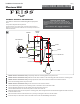
Models VS23701 and VS24701 Only: Temporarily install the mounting plate to the junction box.
Models VS23701 and VS24701 Only: Mark the anchor hole locations on the mounting plate and remove the mounting plate.
Models VS23701 and VS24701 Only: Drill appropriate size holes at the marked locations and install the anchors.
Secure the mounting plate to the junction box.
Models VS23701 and VS24701 Only: Screw the anchor screws into the anchors.
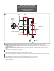
Connect the fixture ground wire to a suitable ground in accordance to local electrical codes.
Connect the white fixture wire to the neutral power line wire with a wire nut.
Connect the black fixture wire to the hot power line wire with a wire nut.
Mount the fixture base onto the top of the mounting plate, then swing the fixture base down flush against the wall and secure
it with the fixture screw.
Place the shade onto the socket and secure it in place by screwing the collar nut onto the socket.
Screw the lamp into the socket. Refer to the label on the socket for Max Wattage Information.
1
2
3
4
5
Monterro Wall
1.0
VS2_70_
VS23701, VS23702, VS23703, VS23704
VS24701, VS24702, VS24703, VS24704
Wall
CAUTION RISK OF FIRE-
This product must be installed in accordance with the
applicable installation code by a person familiar with the
construction and operation of the product and the hazards
involved.
Use minimum 90°c supply conductors.
6
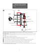
GP I :ENERAL RODUCT NFORMATION
These fixtures are intended to be installed utilizing compliant junctionNEC
boxes.
This product is safety listed for damp locations.
Incandescent lamps may be dimmed with a standard incandescent dimmer.
LED LEDlamps may be dimmed with a dimmer. Consult lamp manufacturer for
additional information.
1A
JUNCTION BOX
MOUNTING PLATE
7
8
FIXTURE SCREW
LAMP
SOCKET
COLLAR NUT
10
7
9
11
SHADE
53
8
9
10
11
53
ANCHOR
ANCHOR
SCREW