P.
General Assembly Guidelines I. Ensure that all parts and hardware are available before beginning assembly. II. Follow each step carefully to ensure the proper assembly of this product. III. Two people are recommended for ease in the assembly of this product. IV. The three main types of hardware used to assemble this product are: wood dowels, screws and bolts. V. The provided glue is to secure wood dowels in place.
Parts List 1 5 2 5 5 5 3 10 9 8 7 6 4 4 16 15 13 14 17 11 12 12 16 15 11 14 13 17 P.
Hardware List A Ø8x30mm Wooden dowel 19 pcs B Ø8x35mm Cam bolt 24 pcs C Ø15x11mm Cam lock 24 pcs Sticker 24 pcs Screw 16 pcs Handle 2 pcs D E Ø6x50mm F G Ø4x22mm Bolt 2 pcs H 4mm Hex Key 1 pc Glass pads 8 pcs pcs J K Ø4x32mm Screw 8 L Ø3x12mm Screw 24 pcs M Ø1/4"x25mm Bolt 12 pcs N Ø1/4"x10mm Bolt 16 pcs P Q Glue tube 1 pc Drawer slider 2 Set * Note: This piece comes preassembled for shipping purposes and must be disassembled to complete assembly.
Step 1 Slider arm Slider arm Slider bracket Q Slider bracket Q Pick up the Ball Bearing Slides (Q) and separate the slide Runner for the following Steps. Extend the Slide Runner all the way forward,press the plastic release lever of the ball bearing Slides up and pull the Slide Runner Complete out . P.
Step 2 L L L L L L Q 14 x2pcs 15 x2pcs Q F 17 x2pcs B G B B B Secure cam bolt (B) into part (17) ,then using bolt (G) attach handle (F) into part (17) and using screw (L) attach slider (Q) into parts (14,15),with Philips head screwdriver as per diagram. P.
Step 3 Finished edge 8 7 L L L L Q L L 9 6 L L Q L L L L Use screw (L) attach slider (Q) into parts (6,7,8,9),with Philips head screwdriver as per diagram. P.
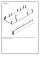
Step 4 A A Finished edge A A 8 7 A A A A A A A B 9 B A A B 6 A B A A Insert wooden dowel (A) into parts (6,7,8,9,) ,then secure cam bolt (B) into parts (6,9) with Philips head screwdriver as per diagram. P.
Step 5 B B B B B B B B 3 B B B A B A A 10 Insert wooden dowel (A) into part (10) ,then secure cam bolt (B) into part (3) with Philips head screwdriver as per diagram. P.
Step 6 H N N 5 2 2 Using bolt (N) attach part (5) into part (2) with hex key (H) as per diagram. Note: Do not tighten all bolts. P.
Step 7 M 5 M H M 5 3 5 M 2 5 Using bolt (M) attach part (3) into part (5) with hex key (H) as per diagram. P.
1 Step 8 2 C 3 9 C 10 C C 6 Using cam lock(C) secure parts (6,9) into part (10) with Philips head screwdriver as per diagram. P.
Step 9 E E 8 H 10 E E 7 Using screw (E) attach part (10) into parts (7,8) with hex key (H) as per diagram. P.
1 Step 10 2 3 C C C 6 7 10 C C C C C C 8 C 9 C 3 C Using cam lock(C) secure parts (6,7,8,9,10) into part (3) with Philips head screwdriver as per diagram. P.
Step 11 E E E E E 4 E E E E E E 6 6 H 4 7 E 8 9 Using screw (E) attach part (4) into parts (6,7,8,9,10) with hex key (H) as per diagram. P.
Step 12 11 11 M 9 H M N N 12 2 9 N M M N H 2 Using bolts (M,N) attach parts (11,12) into parts (2,9) with hex key (H) as per diagram. P.
Step 13 12 M H N 6 12 M N 11 2 M 6 M N H N 2 Using bolt (M,N) attach parts (11,12) into parts (6,2) with hex key (H) as per diagram. Tighten all the bolts. P.
Step 14 x2 14 K K 15 16 K K 13 14 15 Using screw (K) attach parts (14,15) into part (16) with Philips head screwdriver ,then put part (13) as per diagram. P.
Step 15 x2 1 2 3 C 17 C 14 C 15 C Using cam lock(C) secure part (17) into parts (14,15) with Philips head screwdriver as per diagram. P.
Step 16 D D D D Place sticker (D) cover the holes as per diagram . P.
Step 17 OR Slider arm Q Slider bracket Insert the assembled drawers into the unit frame, extend the Ball Bearing Slide Tracks onthe pedestal Side Panel all the way forward .Then align the Slide Runners on the asembled drawers with the Slide Tracks and push the drawer carefully inside until it stops. P.
Step 18 J J J J 2 J J J J J J Tear off and put glass pads (J) as per diagram. P.
Step 19 1 2 Put part (1) as per diagram. P.
Step 20 Final Assembly P.