
User manual


EN
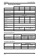
Technical description SinePower
40
I
The inverters have a 230 Vw socket and a connection terminal for perma-
nent connection.
Due to the voltage synchronisation with the AC input voltage, the inverter is
suitable for operating sensitive consumers which react to an irregular voltage
supply.
The device can also be configured with a PC via an RS 232 interface and us-
ing the DIP switches on the device.
The inverter can be switched to an energy-saving mode to prevent the con-
nected battery from discharging too quickly.
Parallel operation allows up to three inverters (of the same model) to run at
the same time.
The inverter can be easily controlled using the remote control (accessory).
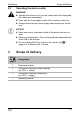
7.1 Control elements
Control elements of the inverter (fig. 5, page 4)
NOTE
The individual values are found in the chapter “Technical data” on
page 54.
Item Description Description
1 Dip switch Makes settings on the inverter (such as
mains voltage, mains frequency, energy-
saving mode).
2 LED See chapter “Status indications” on
page 49
3 Main switch
“ON/OFF/
REMOTE” switch:
Switches the device on, off or to opera-
tion via the remote control (accessory)
4 Fuse Protects the inverter from overload.
The fuse can be pressed in again once it
has triggered.
5 Grounding screw Sets or removes the grounding bridge