
Installation Instructions

EN
Technical description CombiPower
68
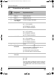
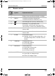
6.2 Connections and controls
No. in
fig. 1,
page 3
Designation Explanation/function
1 POS (+) Positive terminal
2 NEG (–) Negative terminal
3 5A CHARGER/
2.5A charger
5 A/2.5 A charger connection
4 INV. AC OUTPUT 230 V inverter output
L: Live conductor
N: Neutral conductor
FG: Earth connection
5 AC OUTPUT 230 V output
L: Live conductor
N: Neutral conductor
FG: Earth connection
6 AC INPUT 230 V input
L: Live conductor
N: Neutral conductor
FG: Earth connection
7 – Cover
8 CIRCUIT
BREAKER
LS: Circuit breaker (fig. 7, page 5)
The circuit breaker is triggered when there is
excess current or a short circuit.
➤ Eliminate the cause of the fault.
➤ Press the switch to reset the device.
9 CHASSIS
GROUND
Earth connection
10 – Main switch:
0: Off
I: On
The main switch overrides the remote control set-
tings. When the main switch is in the “0” position,
you cannot switch on the device with the remote
control.
_CombiPower_IA_DE-IT.book Seite 68 Freitag, 21. Oktober 2011 8:10 20