
Installation Instructions


EN
CombiPower Connecting the device
85
Connecting the fault display relay
If an alarm occurs, the (common) alarm contact switches to the normally
open contact.
➤ Connect the fault display relay as shown in fig. b, page 8 to the “FAIL-
URE” connection (fig. 1 16, page 3):
– NO: normally open contact
– COM: common contact
– NC: normally closed contact
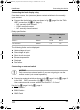
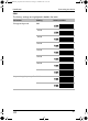
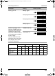
Relay specification:
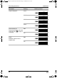
The following faults can be displayed:
Undervoltage at input
Overvoltage at input
Short circuit at output
Excess temperature
Overload
Fan failure
Connecting an external switch
A
NOTICE!
Only connect an external switch if you are not going to use the
remote control (not normal operation).
➤ Connect an external switch as shown in fig. c, page 8 to fig. d, page 8
to the “INV CHR” connection (fig. 1 17, page 3).
Use conductors with a cross section of at least 0.5 – 0.8 mm².
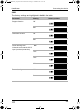
Key for fig. c, page 8 to fig. d, page 8:
ENB
: Enable +
ENB: Enable –
GND: Earth
Maximum voltage Load
Current consumption
NO NC
250 Vw Ohmic 0.5 A 0.5 A
12 V/24 Vg Ohmic 1 A 1 A
_CombiPower_IA_DE-IT.book Seite 85 Freitag, 21. Oktober 2011 8:10 20