
User`s manual


Ground Terminal
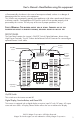
This connection is located on the lower left of the rear panel. It is for attaching a 6 gauge
insulated safety ground wire. This safety wire is for protecting personnel if there is an
unlikely failure in either the cabling or enclosure insulation. Do not directly connect this
ground connection to the negative DC terminal. This safety wire is to be connected to the
vehicle frame or earth ground. This is described in the installation procedure.
PLANNING THE INVERTER SYSTEM
Any large wattage inverter system requires planning before installation. There are several
steps to the planning process so the user must determine the following:
• Maximum inverter wattage required
• Operating time (run time) needed between battery recharges
• Battery bank capacity in amp-hours
• Charger requirement to charge batteries within a practical time.
• Distance between battery bank and inverter.
DETERMINING MAXIMUM APPLIANCE WATTAGE
Maximum AC appliance wattage is the first factor in planning battery and charging systems.
Some background: Large microwave oven specifications list cooking power (watts) and
appliance power. Appliance power is the AC load the inverter has to supply.
Most other electrical tools, appliances and audio/video equipment have labels that list the
unit’s power requirements in watts. If the tool or device is rated in amps, multiply the amps
by 115 (115V AC) to determine the watts. For example, a power tool rated at 4 amps will
draw 460 watts.
Determine the wattage of each appliance you need to simultaneously operate. Add all of
the appliance wattages to obtain an estimated “total watts” number. Remember to consider
the startup surge that motorized appliances will cause. Do not exceed the surge rating of this
inverter (6000 watts). This can cause immediate an overload shutdown.
At 3,000 watts continuous output, this inverter requires a DC power supply (battery bank)
that can continuously supply the following level of amps for the duration of the run time:
#2007-2 (12V DC Input) — 300 amps @ 12V
#2007-4 (24V DC Input) — 150 amps @ 24V
#2007-8 (48V DC Input) — 75 amps @ 48V
CONFIGURING THE BATTERY BANK
To determine the minimum battery ampere-hour rating that you will need to operate
appliances from the inverter, and any DC appliances powered by the battery bank. Follow
these steps:
(The following calculations are specific to 12V systems. For 24V or 48V systems, a different
calculation is required but the same principles should apply)
1. List the maximum continuous wattage that the inverter has to supply.
©2013 Wagan Corporation. All Rights Reserved.
Wagan Tech and wagan.com are trademarks used by Wagan Corporation.
User’s Manual—Read before using this equipment
6
www.wagan.com