studio Pro™ Owner‘s manual read this manual for complete instructions FRANÇais - P. 17 espaÑol - p. 33 wagner-group.com EN F ES 1216 • Form No.
IMPORTANT SAFETY INFORMATION Read all safety information before operating the equipment. Save these instructions. To reduce the risks of fire or explosion, electrical shock and the injury to persons, read and understand all instructions included in this manual. Be familiar with the controls and proper usage of the equipment. EXPLANATION OF SYMBOLS Indicates a hazardous situation which, if not avoided, could result in death or serious injury.
IMPORTANT SAFETY INFORMATION WARNING - To reduce the risk of fire or explosion: •• •• •• •• •• •• •• •• •• •• Do not spray flammable or combustible materials near an open flame, pilot lights or sources of ignition such as hot objects, cigarettes, motors, electrical equipment and electrical appliances. Avoid creating sparks from connecting and disconnecting power cords.
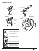
OVERVIEW i 1. 2. 3. In order to set up the system, items will need to be retrieved from inside of the X-Boost Power Box. Lower the carry handle by pressing the locking tabs on either side of the handle. Open the Power Box (a). Open the air hose retainer (b) inside the cover and retrieve the air hose and handle assembly (c). Close the air hose retainer. Unwrap the power cord. Slide the power cord into the provided recess.
CONTROLS AND FUNCTIONS Control Finish Nozzle Air cap Handle / air hose assembly X-Boost Power Dial Material flow control Trigger ON/OFF switch ON/OFF switch Material container iSpray Nozzle X-Boost Power Box Handle Spray width lever Spray gun holder Material flow control Trigger Adjustment ring Material container Turbine ON/OFF switch The turbine ON/OFF switch turns the system’s main power ON (I) and OFF (0). Note: The turbine will not turn ON with this switch.
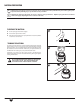
MATERIAL PREPARATION i Material to be sprayed may need to be strained to remove any impurities in the paint which may enter and clog the system. Impurities in the paint will give poor performance and a poor finish. i Only thin the material if absolutely necessary to improve spray performance. Optimal spray performance should be acheived simply by adjusting the various controls on the unit. TO PREPARE THE MATERIAL 1. 2. 3. Stir the spraying material thoroughly. Unscrew the cup from the nozzle.
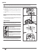
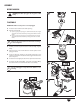
ASSEMBLY Before you begin NEVER point the spray gun at any part of the body. 1 To Assemble IMPORTANT: Make sure the power cord is unplugged. 1. 2. Insert the suction tube into the intake opening. Align the suction tube a. If you are going to be spraying in a downward direction, the angled end of the suction tube should be pointing toward the front of the nozzle. 2 b.
POWER AND MATERIAL CONTROLS Spray performance will depend upon a number of factors: material thickness, air power, spray pattern selected, and material flow. Testing different variations of the control settings will help you achieve the desired results. See descriptions and suggested Power and Material Settings Guide below to help with your project. i X-Boost™ Power Dial The X-Boost™ Power Dial adjusts the level of air pressure produced by the turbine.
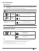
SPRAY PATTERN ADJUSTMENT Adjust Spray Shape i The spray pattern shape is adjusted by turning the adjustment ring (iSpray) or air cap ears (Control Finish) to either the vertical, horizontal, or diagonal positions. The positions of the air cap and the corresponding spray pattern shapes are illustrated below. Test each pattern and use whichever pattern is suitable for your application. never trigger the gun while adjusting the ears on the air cap. NEVER point the spray gun at any part of the body.
PROPER SPRAYING TECHNIQUE STOP The item you are spraying must be properly masked in order to prevent overspray from covering woodwork, floors or other furnishings. If spraying with an air-assisted spray system is new or unfamiliar to you, it is advisable to practice on a piece of scrap wood or cardboard before beginning on your intended workpiece and/or test with water. Surface Preparation All objects to be sprayed should be thoroughly cleaned before spraying material on them.
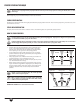
PROPER SPRAYING TECHNIQUE (continued) Pattern Examples Use the images and guidelines below in order to assist you in achieving the desired spray pattern for your project. These are meant to be general starting points - you may have to slightly modify certain controls on the system in order to get the exact performance you need. STOP During a project, periodically wipe the nozzle tip with a cloth to remove any dried paint.
CLEANUP Flushing the unit 1 Before you begin When cleaning, use the appropriate cleaning solution (warm, soapy water for latex materials; mineral spirits for oil-based materials) 1/2 important: Never clean air cap or air holes in the nozzle with sharp metal objects. Do not use solvents or lubricants containing silicone. PULL Special cleanup instructions for use with flammable solvents (must have a flashpoint above 100ºF (38ºC): •• •• •• •• 2 Always flush spray gun outside.
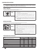
CLEANUP (continued) Cleaning the Nozzle 1. 2. Make sure power cord is unplugged. Remove the air hose from the turbine. iSpray nozzle only - 1 a. Remove the adjustment ring (a) carefully from the connecting nut (b). Loosen the connecting nut. b. Remove the parts as shown. Clean all parts with a cleaning brush and the appropriate cleaning solution. 3. To reassemble, see the instructions on the next page. Control Finish nozzle only a. Unscrew the nut and remove the air cap and nozzle.
REASSEMBLY To Reassemble 1. Insert the nozzle (1). Make sure to align the groove (a) and notch (b) and align the nozzle opening with the needle. i 2. Groove This step is easier if the iSpray nozzle is facing up. Make sure that the two recesses on the adjustment ring are engaged in the air cap tabs. 1 (a) Snap the adjustment ring (4) into the connecting nut (3), enabling the adjustment lever (f) on the peg (g) to be positioned in the air cap. i 4. (c) 1 Put the air screen (d) in the air cap (e).
MAINTENANCE Cleaning the FILTER important: Before every use, you should inspect the air filter in the turbine to see if it is excessively dirty. If it is dirty, follow these steps to replace it. important: Never operate your unit without the air filter. Dirt could be sucked in and interfere with the function of the unit. 1. Open up the Power Box cover. Press the tab and remove the filter cover. 2. Remove the dirty filter from the turbine and replace.
TROUBLESHOOTING PROBLEM CAUSE SOLUTION Problem A: Little or no material flow 1. 2. 3. 4. 5. 6. 7. 8. Nozzle clogged. Suction tube clogged. Material flow setting too low. Suction tube loose. No pressure build up in container. Air filter clogged. Spray material too thick. Nozzle seal missing or worn. 1. 2. 3. 4. 5. 6. 7. 8. Clean. Clean. Increase material flow setting. Remove and replace as tightly as possible. Tighten container. Change Thin*. Replace (extras provided). Problem B: Material leaking 1.
Parts List • Liste de pièces • Lista de piezas 2 1 3 # Part No. English Nº de piéce Description Pieza No. Français Description Español Descripción 1 ------- 2 3 Qty. Qte. Cant.
Parts List • Liste de pièces • Lista de piezas iSpray Nozzle • Buse de iSpray • Boquilla de iSpray 1 2 3 4 8 6 7 5 # 50 Part No. Nº de piéce Pieza No.
Parts List • Liste de pièces • Lista de piezas Control Finish Nozzle • Buse de Control Finish • Boquilla de Control Finish 1 2 4 3 5 9 7 8 6 # Part No. Nº de piéce Pieza No. English Description Français Description Español Descripción 1 Qty. Qte. Cant.
Limited Warranty HVLP paint spray equipment This product, manufactured by Wagner Spray Tech Corporation (Wagner), is warranted against defects in material and work-manship for one year following date of purchase if operated in accordance with Wagner’s printed recommendations and instructions. This warranty does not cover damage resulting from improper use, accidents, user’s negligence or normal wear.
Notes • remarques • notas ES F EN 55
studio Pro™ wagner-group.