SERVICE/OPERATION MANUAL Form No.
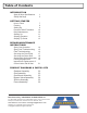
Table of Contents INTRODUCTION Spray & Stripe Specifications Safety Warnings 1 2 GETTING STARTED How to Flush Flushing Setting Up Pressure Relief Procedure Daily Maintenance Starting Up Striping Operation Striping Tip Guide 7 8 9 10 10 11 12 13 REPAIRS/MAINTENANCE INSTRUCTIONS Spray Gun Operation Spray Gun Troubleshooting Field Troubleshooting Servicing the Fluid Pump Servicing the Piston Rod Servicing the Suction Assembly Packing Replacement Inspection & Replacement of Control Valve, Ball & Seat 14 15
Introduction INTRODUCTION The heart of the Spray & Stripe series is the time tested and contractor proven Airlessco “LP” piston paint pump. Designed for spraying 1700 gallons per year, this pump is used daily by thousands of painting professionals worldwide--with a reputation for trouble free performance that’s unmatched in the industry. They’re small, compact, easy to use, and quick to clean. Even changing colors is a breeze. Stripe with water-based paints made for traffic lines or athletic fields.
Safety Warnings TOXIC FLUID HAZARD Hazardous fluid or toxic fumes can cause serious injury or death if splashed in eyes or on skin, inhaled or swallowed. Know the hazards of the fluid you are using. Store & dispose of hazardous fluids according to manufacturer, local, state & national guidelines. ALWAYS wear protective eye wear, gloves, clothing and respirator as recommended by fluid manufacturer. ALWAYS INSPECT SPRAYING AREA • ALWAYS keep spraying area free from obstructions.
Safety Warnings HIGH PRESSURE SPRAY CAN CAUSE EXTREMELY SERIOUS INJURY. OBSERVE ALL WARNINGS. INJECTION HAZARD Fluids under high pressure from spray or leaks can penetrate the skin and cause extremely serious injury, including the need for amputation. • NEVER point the spray gun at anyone or any part of the body. • NEVER put hands or fingers over the spray tip. Do not use a rag or any other material over your fingers. Paint will penetrate through material and into the hand.
Safety Warnings GROUNDING Ground the sprayer and other components in the system to reduce the risk of static sparking, fire or explosion which can result in serious bodily injury and property damage. Always ground all of these components: • Fluid Hose: use only grounded hoses. • Spray gun or dispensing valve: grounding is obtained through connection to a properly grounded fluid hose and pump. • Object being sprayed: according to your local code.
Safety Warnings FLUSHING Reduce risk of injection injury, static sparking or splashing by following the specific cleaning procedure on page 7. • ALWAYS follow the PRESSURE RELIEF PROCEDURE on page 10. • ALWAYS remove the spray tip before flushing. Hold a metal part of the gun firmly to the side of a metal pail and use the lowest possible fluid pressure during flushing. • NEVER use cleaning solvents with flash points below 140º F. Some of these are: acetone, benzene, ether, gasoline and naphtha.
Safety Warnings WHEN TRANSPORTING EQUIPMENT • Transport with fuel tank EMPTY or with fuel shut-off valve OFF. WHEN STORING GASOLINE OR EQUIPMENT WITH FUEL IN TANK • Store away from furnaces, stoves, water heaters and other appliances that have pilot lights or other ignition source. They can ignite gasoline vapors. Starting engine creates sparking. Sparking can ignite nearby flammable gases. Explosion and fire could result. • If there is natural or LP gas leakage in area, do not start engine.
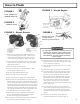
How to Flush FIGURE 1 FIGURE 3 - Honda Engine LOCK TRIGGER TO REMOVE SPRAY TIP FIGURE 2 CONTROL VALVE FIGURE 3 - Briggs Engine FIGURE 4 Maintain firm metal to metal contact between gun and container. 1. Be sure the gun safety latch is engaged and there is no spray tip in the gun. Refer to Fig. 1. Refer to your separate instruction manual provided with your gun on its safety features and how to engage safety latch. 2.
Flushing Read prior to using your sprayer 1. New Sprayer Your Airlessco unit was factory tested in an antifreeze solution which was left in the pump. Before using oil-base paint, flush with mineral spirits only. Before using water-base paint flush with soapy water, then do a clean water flush. 2. Changing Colors Flush with a compatible solvent such as mineral spirits or water. 3. Changing from Water-Base to Oil-Base Paint Flush with soapy water, then mineral spirits. 4.
Setting Up to Stripe or Spray 1. Connect the hose and gun. a. If the hose is not already installed on the striper, remove the plastic cap plug from the outlet tee at the spray pump, and screw a conductive or grounded 3000 psi airless spray hose onto fluid outlet. b. Connect an airless spray gun to the other end of the hose. c. Do not use steel braided airless hose. Use nylon braided airless hose only. NOTE: Do not use thread sealer on swivel unions as they are made to self-seal.
Pressure Relief Procedure To avoid possible serious bodily injury, including injection, always follow this procedure whenever the sprayer is shut off, when checking or servicing it, when installing or changing the tips, whenever you stop spraying or when you are instructed to relieve the pressure. 1. Engage gun safety latch. Refer to instruction manual provided with your gun on its safety features and how to engage safety latch. 2. Turn engine off using OFF switch on the engine. 3.
Starting Up 1. Learn how to operate the control valve. The control valve sets the prime or pressure position as well as the spraying pressure. When the valve is fully counter-clockwise the unit is in the prime position. As the control valve is turned clockwise, the unit’s output pressure to the gun is gradually increased until the control valve is fully clockwise and the unit is at it’s maximum output pressure of 2500 psi. This will fully atomize any stain or paint without needing to dilute the material.
Striping Operation 1. Choose handle location The choices are, installing the handle opposite of the single wheel assembly (standard set up) or placing the handle directly over the single wheel assembly. The handle location is really a matter of personal preference, however having the handle away from the single wheel assembly allows for easier loading/unloading from a van. 2.
Striping Tip Guide Rev-Tip for Striping STRIPING TIP - ORIFICE SIZE (Inches) TM Fan Width (6” from surface) (mm) in .011 .013 .009 25-51 1-2 2-4 4-6 6-8 .015 .017 .021 .019 .023 .025 .027 Latex Latex Latex .031 .035 113ST 115ST 117ST 119ST 51-102 215ST 217ST 219ST 221ST 102-152 152-203 315ST 317ST 319ST 321ST Oil Base Oil Base Latex Striping Paint Latex Latex Water Flow Rate (gpm) (water @ 2000psi, 138 bar) (lpm) .12 .49 .18 .69 .24 .91 .31 1.17 .38 1.47 .47 1.79 .57 .67 2.
Spray Gun Operation SPRAY GUN Attach spray gun to airless unit and tighten fittings securely. Set the gun safety latch. (Also may be called gun safety lock, or trigger lock) * The gun safety latch should always be set when the gun is not being triggered. Read all warnings and safety precautions supplied with the spray gun and in product manual. MAJOR COMPONENTS OF SPRAY GUN & REVERSIBLE REV-TIP™ ™ Reversible Spray Tip Tip Guard Gun Safety Latch or Lock Trigger Guard Gun Handle.
Spray Gun Troubleshooting DEFECTS CAUSE CORRECTION Coarse spray Low pressure Increase the pressure Excessive fogging (overspray) High pressure Material too thin Reduce pressure for satisfactory pattern Use less thinner Pattern too wide Spray angle too large Use smaller spray angle tip Pattern too narrow Spray angle too small Use larger spray angle tip.
Field Troubleshooting PROBLEM Unit doesn't prime CAUSE Airleak due to: • Loose Suction Nut • Worn O-Rings • Hole in Suction Hose Unit primes but has no or poor pressure Unit does not maintain good spraying pressure 16 SOLUTION • Tighten Suction Nut • Replace O-Ring (106-011) on suction seat, & O-Ring (106020) below suction seat • Replace Suction Hose (331-290) Stuck or Fouled Balls Service outlet valve suction assembly Pressure set too low Turn up pressure Filter(s) are clogged Clean or replace
Servicing the Fluid Pump Fluid Pump Disconnect Fluid Pump Reinstall Refer to Figure 1 & 4 Refer to Figure 1 1. Loosen the packing nut and ensure that the piston rod (331-093) is in its upper position in the fluid pump body 2. Flush the material you are spraying out of the machine. (331-011). Slip the sleeve (331-117) & the retaining ring (331-062) over the piston rod. 3. Remove the connecting rod shield (331-111). 1. Follow the Pressure Relief Procedure on page 10. 4.
Servicing the Piston Rod - Outlet Valve FIGURE 3 DISASSEMBLY OF THE OUTLET VALVE REFER TO FIGURE 3 Piston 1. Disconnect the Fluid Pump following instructions on page 17 . 331-195 2. Place piston holder (331-195) in a vise. Slide piston into the holder & lock in place with a 3/8” dowel (331-196). 3. Use a 1/4” allen wrench to unscrew the outlet seat retainer (331-026) from the piston. 331-196 4. Remove the outlet seat (331-026), O-ring (331-100) and outlet ball (331-027). 5.
Packing Replacement Procedures Fluid Pump Removal - Refer to Figure 1 1. Follow the Pressure Relief Procedure on page 9. 2. Flush material you are spraying out of the machine. 3. Remove the connecting rod shield (331-111). 4. Move the piston rod (331-093) to its lowest position by cycling pump slowly. 5. Remove the retaining ring (331-062) from the connecting rod (331-038) and slide the sleeve (331-117) down revealing the connecting rod pin (331-065). 6.
Packing Replacement Procedures 3. Push the two bolts (100-318) through the tube spacers (331-074) & screw into the cover assembly (331-234). Using a 1/2” wrench, tighten the two bolts evenly (alternating between them) until you reach 20 ft-lbs. 4. Reassemble lower suction valve assembly by placing the suction seat (331-409) O-ring (106-011), suction ball (331-030) and suction ball guide (331-029) in the suction nut (331-034) & screw onto the fluid pump body. 5.
Inspection & Replacement of Control Valve, Ball & Seat 1. Use a wrench to unscrew the control valve with ring seal. 2. Make sure that the control valve knob turns freely and that its stem is not worn unevenly, mushroomed or otherwise damaged. 3. Remove TC guide, verify that it is unbroken, clean and notch side is up. 4. Remove control ball. Inspect for any cuts, scratches, chips, rust or other damage. 5. Use a 7/16” allen wrench to unscrew the control seat from the valve body.
Gear Box Assembly - Part No.
Spray Gun Assembly - Part No. 305-280 Part Number 100-011 116-103 120-115 305-275 305-280 561-025 561-026 563-317ST 560-517 - Description Airless 1/4” x 50’ Hose Cable Retainer Spring 008 Silver Gun w/o Tip Gun Mount Ass’y Spray Gun Assembly Rev-Tip Male Seal Rev- Tip Seal Striping Tip Painting Tip (not installed) 116-103 Gun Mount Assembly - Part No. 305-275 Part Number Description 100-342 .321 x 1.25 LG. Screw 116-100 Compression Spring HexScrew .25-20UNC-2A x 1.88 119-049 LG.
Bypass Valve Assembly Part No. 305-264 Part Number 100-040 115-016 115-017 115-024 115-028 115-031 188-377 305-194 24 Description Hose, Whip Control Valve Seat Ass’y Ball Unloader Valve Stat-O-Seal Guide T.C. Return Tube PR Regulator Housing Qty.
Suction Assembly Part No. 331-290 Part Number 106-020 141-015 331-034 331-035 331-217 Description Teflon O-Ring Hose Clamp (some models only) Suction Nut Suction Elbow Suction Filter Qty.
Frame Assembly Part No. 305-213 301-533 Paint Bucket Lid 26 Part Number Description Qty. Part Number Description Qty. 100-317 Nut 5/16-18 Centerlock 4 301-165 Wheel 3 100-320 Wing Screw, 3/8 1 301-170 Axel, 22 5/8” 1 100-370 Screw, Hex Cap 2 301-547 Screw, HXHD 4 113-031 Spacer, 5/8 x 1.
! W NE Reversible REV-TIP Quick Flush ™ Part # 560-xxx REV-TIP for Spray Painting 562-xxxST REV-TIP for Striping Cuts Cleaning Time & Saves Paint ! POSI-LOC SYSTEM ™ Snap in centering of tip. No leaks, splashback or mess. Part # 170-005 Simple to Use...Fast to Finish! SEAL LOCATING HANDLE Tip handle simplifies installing & aligning the seal. EASIEST ASSEMBLY Fewer parts - Less complicated takes only seconds! Each tip individually tested! INTERCHANGEABLE Can be used with most tip guards.
ACCESSORIES AIRLESSCO PUMP CONDITIONER Should be used on piston pumps between uses to prevent paint from drying on the piston & causing packing wear. STAY CLEAN™ to Spray protectant for your machine to prevent paint from sticking to it. 114-030 20 oz. can Display of 48 - 1 oz. bottles 1 quart bottle 1 Gallon bottle 010-001 010-009 010-019 Case order quantity: 12 on quarts, 4 on gallons PAINT STRAINERS Prefilter your paint using strainer bags. One dozen per pack.