Originalbetriebsanleitung Airless high-pressure spraying unit Operating manual 2 Airless – Hochdruck Spritzgerät Betriebsanleitung 32 Super Finish 23 PLUS 110V / 50 Hz 2346 191 2346676 07 / 2014 2346 192
Super Finish 23 PLUS GB Translation of the original operating instructions WARNING! Attention, danger of injury by injection! Airless units develop extremely high spray pressures. 1 2 3 Never bring fingers, hands or other body parts into contact with the spray jet! Never point the spray gun at yourself, other persons or animals. Never use the spray gun without spray jet safety guard. Do not treat a spray injury as a harmless cut.
Super Finish 23 PLUS GB CONTENTS Contents 1 1.1 1.2 1.3 1.4 1.5 1.6 1.7 1.8 1.9 1.10 1.11 1.12 1.13 1.14 1.15 1.16 1.17 1.18 1.19 1.
Super Finish 23 PLUS GB SAFETY REGULATIONS 1 SAFETY REGULATIONS FOR AIRLESS SPRAYING 1.4 Attention, danger of injury by injection! Never point the spray gun at yourself, other persons or animals. Never use the spray gun without spray jet safety guard. The spray jet must not come into contact with any part of the body. In working with Airless spray guns, the high spray pressures arising can cause very dangerous injuries.
Super Finish 23 PLUS GB SAFETY REGULATIONS 1.9 MAX. OPERATING PRESSURE 1.12 USE OF UNITS ON BUILDING SITES AND WORKSHOPS The permissible operating pressure for the spray gun, spray gun accessories, unit accessories and high-pressure hose must not fall short of the maximum operating pressure of 25 MPa (250 bar or 3625 psi). Use a manometer that is suited for this pressure. The unit may only be connected to the mains network via a special feeding point with a residual-current device with INF ≤ 30 mA.
Super Finish 23 PLUS GB SAFETY REGULATIONS 1.19 WORK AT ELECTRICAL COMPONENTS Unplug the power plug from the outlet before carrying out any repair work. 1.20 SETUP ON AN UNEVEN SURFACE The front end must always point downwards in order to avoid sliding away. If possible do not use the unit on an inclined surface since the unit tends to wander through the resulting vibrations. 2 2.
Super Finish 23 PLUS GB GENERAL VIEW OF APPLICATION 2.2.2 3.2 FILTERING Sufficient filtering is required for fault-free operation. To this purpose the unit is equipped with a suction filter (Item 1) and an insertion filter in the spray gun (Item 2). Regular inspection of these filters for damage or soiling is urgently recommended. A high-pressure filter (Item 3) -available as accessory- is rising up the filtering surface and will make the work more comfortable.
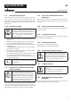
Super Finish 23 PLUS GB DESCRIPTION OF UNIT 3.3 1 2 3 4 5 6 7 1 EXPLANATORY DIAGRAM Tip guard with airless tip Spray gun High-pressure hose Connection for high-pressure hose Pressure gauge Pressure control valve Multifunction switch 2 3 12 Symbols (shown in the recess of the switch): 0 OFF 11 ON / Circulation 6 ON / Spraying 8 9 10 11 12 13 9 Return tube Suction tube Hopper Inlet valve button Outlet valve PumpRunner 3.
Super Finish 23 PLUS GB DESCRIPTION OF UNIT 3.5 3.6 TROLLEY BACKFITTING Before start with the backfitting, pull of main plug of socket, disassemble suction system and high pressure hose When changing between the top container and the suction system, the carriage needs to be altered. 1. Unscrew the screws (pos. 1) with the attached wrench (17 mm). 2. Tilt the shaft and align the Super Finish 23 PLUS in the required position: a) Operate with suction system b) Operate with top container 3.
Super Finish 23 PLUS GB STARTUP 4 4.1 STARTUP 4.3 1. Screw the high pressure hose (9) onto the hose connection 2. Screw the spray gun (10) onto the high pressure hose 3. Tighten all union nuts on high pressure hose so that no coating material can escape. 4. Screw the tip holder with the selected tip onto the spray gun, align tip and tighten union nut. UNIT WITH SUCTION SYSTEM 1. Ensure that the sealing surfaces of the connections are clean.
Super Finish 23 PLUS GB STARTUP 4.5 CLEANING PRESERVING AGENT WHEN STARTING-UP OF OPERATION INITIALLY Unit with suction tube 1. Immerse the suction system into a container filled with a suitable cleaning agent (recommendation: water). Unit with hopper 2. Fill up hopper with a suitable cleaning agent (recommendation: water). 3. Set multifunction switch (1) to (ON– circulation); the unit commences to run. 4. Turn the pressure regulating knob (2) to the right until the stop is reached. 5.
Super Finish 23 PLUS GB SPRAYING TECHNIQUE / HANDLING THE HIGH-PRESSURE HOSE / INTERRUPTION OF WORK 5 SPRAYING TECHNOLOGY Move the spray gun evenly during the spraying process. If this is not observed, an irregular spraying appearance will be the result. Carry out the movement with the arm, not with the wrist. A parallel distance of approx. 30 cm between the tip and the surface to be coated should always be observed. The lateral limitation of the spray fan should not to be too distinct.
Super Finish 23 PLUS GB DISPLAYS AT THE UNIT / CLEANING THE UNIT 8 CLEANING THE UNIT A clean state is the best method of ensuring operation without problems. After you have finished spraying, clean the unit. Under no circumstances may coating material rests dry and harden in the unit. The cleaning agent used for cleaning (only with a flash point above 21 °C) must be suitable for the coating material used. • • 1. 2. 3. 4. 5. 6. Secure the spray gun, refer to the operating manual of the spray gun.
Super Finish 23 PLUS GB CLEANING THE UNIT 8.1 8.3 CLEANING THE UNIT FROM THE OUTSIDE First unplug the power plug from the outlet. Danger of short-circuits caused by water ingression! Never spray down the unit with high-pressure or high-pressure steam cleaners. Do not put the high-pressure hose into solvents. Use only a wet cloth to wipe down the outside of the hose. Wipe down unit externally with a cloth which has been immersed in a suitable cleaning agent. 8.
Super Finish 23 PLUS GB CLEANING THE UNIT / SERVICING 8.4 CLEANING THE AIRLESS SPRAY GUN 1. Rinse the Airless spray gun with a suitable cleaning agent under lower operating pressure. 2. Clean the tip thoroughly with a suitable cleaning agent so that no suitable coating material rests remain. 3. Do not store the tip in solvent because this reduces the durability considerably. 4. Clean the outside of the Airless spray gun thoroughly. 9 9.
Super Finish 23 PLUS GB REPAIRS AT THE UNIT 10 REPAIRS AT THE UNIT Switch the unit off. Before all repair work: Unplug the power plug from the outlet. 10.1 INLET VALVE PUSHER 1. Use a 17 mm spanner to screw out the inlet valve button. 2. Replace the wiper (1) and O-ring (2). Installation 1. Insert the inlet valve (2) into the trigger housing (1) and secure with the clasp (3). Ensure that the (black) seal (5) is mounted in the trigger housing. 2.
Super Finish 23 PLUS GB REPAIRS AT THE UNIT 10.3 10.4 OUTLET VALVE 1. Use a 22 mm wrench to screw the outlet valve from the paint section. 2. Carefully pull of the clasp (1) using the enclosed screwdriver. The compression spring (2) presses ball (4) and valve seat (5) out. 3. Clean or replace the components. 4. Check the O-ring (7) for damage. 5. Check the installation position when mounting the spring support ring (3) (clipped onto spring (2)), outlet valve seat (5) and seal (6), refer to figure.
Super Finish 23 PLUS GB REPAIRS AT THE UNIT 10.5 This may only be carried out by a skilled electrician. No liability is assumed for incorrect installation. Switch the unit off. Before all repair work: Unplug the power plug from the outlet. 1. In models with a front cover unscrew the trigger housing with inlet valve (1) from the paint section (see inlet valve, 10.2, sections 1 to 3) and remove the front cover (2) by unscrewing the screws. 2. Remove the multi-function switch (3) by unscrewing the screws.
green/yellow black white POWER CABLE 110V / 50 Hz black U2 Z2 C = 65µF 425V 1~ M 155°C black OPERATION CAPACITORS C = 50µF 250V black blue MOTOR WITH TEMPERATURE SWITCH U1/Z1 green/yellow light blue light blue red NO black red MICRO SWITCH COM NC blue brown 10.
Super Finish 23 PLUS GB REPAIRS AT THE UNIT 10.
Super Finish 23 PLUS GB SPARE PARTS AND ACCESSORIES 11 11.1 SPARE PARTS AND ACCESSORIES 9 SUPER FINISH 23 PLUS ACCESSORIES 1 10 5 2 6 11 12 3 4 13 14 7 8 15 Accessories: ITEM DESIGNATION ORDER NO. ITEM. DESIGNATION 1 Spray gun AG-14 (stainless steel) Spray gun AG-08 (aluminium made) 0502 166 9 2 AirCoat spray gun AC 4600 (blue) 0394 156 Tip extension Length 15 cm Length 30 cm Length 45 cm Length 60 cm 0556 051 0556 052 0556 053 0556 054 3 Double hose 9984 564 10 HP hose DN-3, 7.
Super Finish 23 PLUS GB SPARE PARTS AND ACCESSORIES GB Airless tip table Wagner TradeTip 3 tip up to 270 bar (27 MPa) i without tip F thread (11/16 - 16 UN) for Wagner spray guns Order no. 0289391 without tip G thread (7/8 - 14 UN) for Graco/Titan spray guns Order no. 0289390 All of the tips in the table below are supplied together with the appropriate gun filter. Application Tip marking Spray angle Bore inch / mm Spraying width mm 1) Gun filter Order no.
Super Finish 23 PLUS GB SPARE PARTS AND ACCESSORIES i All of the tips in the table below are supplied together with the appropriate gun filter. Application Tip marking Spray angle Bore inch / mm Spraying width mm 1) Gun filter Order no. Roof coatings 223 323 423 523 623 723 823 20° 30° 40° 50° 60° 70° 80° 0.023 / 0.58 0.023 / 0.58 0.023 / 0.58 0.023 / 0.58 0.023 / 0.58 0.023 / 0.58 0.023 / 0.
Super Finish 23 PLUS GB SPARE PARTS AND ACCESSORIES 2SpeedTip The innovative changeover nozzle from WAGNER combines two nozzle cores into one nozzle. 2 Speed Tip holder Order no. 0271065 Tip table Object size Painting material Lacquer (L) Emulsion (D) Filler (S) D5 Nozzles: 111 / 415 Order no. 0271 062 S5 Nozzles: 225 / 629 Order no. 0271 064 D7 Nozzles: 113 / 417 Order no. 0271 063 Small L10 Nozzles: 208 / 510 Order no. 0271 042 D10 Nozzles: 111 / 419 Order no.
Super Finish 23 PLUS GB SPARE PARTS AND ACCESSORIES 11.2 SPARE PARTS LIST HIGH-PRESSURE FILTER 11.3 SPARE PARTS LIST TROLLEY ITEM ORDER NO. DESIGNATION ITEM ORDER NO. DESIGNATION 1 0097 121 High-pressure filter HF- 01 compl. 1 2343 670 Trolley assy. (SF 23 PLUS) 2 0097 301 Filter block 2 9910 208 Hexagon nut M8 3 0097 302 Filter housing 3 9920 102 Washer A 8.
Super Finish 23 PLUS GB SPARE PARTS AND ACCESSORIES 11.4 SPARE PARTS LIST SF 23 PLUS ITEM ORDER-NO DESIGNATION 35 9904 306 Lock screw 1 0340 339 Inlet 36 9970 218 Sealing ring 2 2334 383 Inlet valve trigger housing 37 2341 465 Label (right) 3 0341 336 Clasp 38 0340 257 Pressure gauge cpl. (incl. pos. 39,40,41) 4 9971 486 O-ring 39 9991 956 Pressure gauge 5 0341 316 Wiper 40 9970 109 Sealing ring 6 2337 033 Inlet valve trigger (incl. pos.
18 17 14 13 16 15 12 9 6 8 11 3 2 7 10 21 23 25 20 22 24 26 5 19 4 1 37 36 35 40 41 39 17 27 34 10 28 38 29 17 32 31 30 33 Super Finish 23 PLUS GB SPARE PARTS AND ACCESSORIES Spare parts diagram SF 23 PLUS 27
Super Finish 23 PLUS GB SPARE PARTS AND ACCESSORIES 11.5 11.6 SPARE PARTS LIST FRAME SPARE PARTS LIST SUCTION SYSTEM (RIGID) POS. BESTELL-NR BENENNUNG POS. BESTELL-NR BENENNUNG 1 2343 637 Frame complete 1 2342 879 Suction system assy.. 2 9900 118 Hexagon screw M8x30 3 9920 102 Washer A 8.
Super Finish 23 PLUS GB SPARE PARTS AND ACCESSORIES 11.7 SPARE PARTS LIST HOPPER 5L 11.8 SPARE PARTS LIST HOPPER WITH TOPCLEAN ITEM ORDER-NO DESIGNATION ITEM ORDER-NO DESIGNATION - 0341 265 Hopper 5l, assy. - 0341 268 Hopper 5l with TopClean, assy. 1 0340 901 Cover 1 0340 904 Hopper 5l (filter disc see 11.7) 0037 607 2 0340 901 Cover 0003 756 Filter disk, mesh width 0,8 mm Optional: Filter disk, mesh width 0,4 mm 3 0340 271 TopClean, assy.
Super Finish 23 PLUS GB TESTING OF THE UNIT / INFORMATION ON PRODUCT LIABILITY / GUARANTEE DECLARATION TESTING OF THE UNIT GUARANTEE DECLARATION For safety reasons, we would recommend having the device checked by an expert as required but at least every 12 months to ensure that it can continue to operate safely. In the case of unused devices, the check can be postponed until they are next started up. All (potentially deviating) national inspection and maintenance regulations must also be observed.
Super Finish 23 PLUS GB GUARANTEE DECLARATION claims must be made immediately, or at the latest within a period of 2 weeks. The authorised specialist shop that delivered the device is entitled to accept guarantee claims. Guarantee claims may also be made to the service centres named in our operating instructions. The product has to be sent without charge or presented together with the original purchase document that includes details of the purchase date and the name of the product.
Super Finish 23 PLUS D Originalbetriebsanleitung Warnung! Achtung, Verletzungsgefahr durch Injektion! Airless-Geräte entwickeln extrem hohe Spritzdrücke. 1 2 3 32 Niemals Finger, Hände oder andere Körperteile mit dem Spritzstrahl in Berührung bringen! Nie die Spritzpistole auf sich, Personen und Tiere richten. Nie die Spritzpistole ohne Spritzstrahl-Berührungsschutz benutzen. Behandeln Sie eine Spritzverletzung nicht als harmlose Schnittverletzung.
Super Finish 23 PLUS D INHALTSVERZEICHNIS Inhaltsverzeichnis 1 1.1 1.2 1.3 1.4 1.5 1.6 1.7 1.8 1.9 1.10 1.11 1.12 1.13 1.14 1.15 1.16 1.17 1.18 1.19 1.
Super Finish 23 PLUS D SICHERHEITSVORSCHRIFTEN 1 SICHERHEITSVORSCHRIFTEN FÜR DAS AIRLESS-SPRITZEN 1.4 Achtung Verletzungsgefahr durch Injektion! Nie die Spritzpistole auf sich, Personen und Tiere richten. Nie die Spritzpistole ohne Spritzstrahl-Berührungsschutz benutzen. Spritzstrahl darf mit keinem Körperteil in Berührung kommen. Bei Airless-Spritzpistolen auftretende hohe Spritzdrücke können sehr gefährliche Verletzungen verursachen.
Super Finish 23 PLUS D SICHERHEITSVORSCHRIFTEN 1.9 MAX. BETRIEBSDRUCK Der zulässige Betriebsdruck für die Spritzpistole, Spritzpistolenzubehör, Gerätezubehör und Hochdruckschlauch darf nicht unter dem am Gerät angegebenen maximalen Betriebsdruck von 25 MPa (250 bar) liegen. Betreiben Sie das Gerät mit einem für diesen Druckbereich geeigneten Manometer. 1.
Super Finish 23 PLUS D ANWENDUNGSÜBERSICHT 1.20 AUFSTELLUNG IN UNEBENEM GELÄNDE Die Vorderseite muss nach unten zeigen, um ein Wegrutschen zu vermeiden. Auf schrägen Untergründen ist das Gerät nicht zu betreiben, da es durch Vibrationen zum Wandern neigt. Die Geräteleistung der Super Finish 23 PLUS ist so konzipiert, dass die Verarbeitung von Dispersionen im Innenbereich für kleine bis mittlere Objekte möglich ist. Im Lackierbereich eignen sich das Gerät für alle üblichen Arbeiten wie z.B.
Super Finish 23 PLUS D GERÄTEBESCHREIBUNG 2.2.2 3.2 FILTERUNG Für einen störungsfreien Betrieb ist eine ausreichende Filterung erforderlich. Dazu ist das Gerät mit einem Ansaugfilter (Pos. 1), und einem Einsteckfilter in der Spritzpistole (Pos. 2) aufgestattet. Eine regelmäßige Kontrolle dieser Filter auf Beschädigung oder Verschmutzung ist dringend zu empfehlen. Ein im Zubehör erhältlicher Hochdruckfilter (Pos. 3) vergrößert die Filterfläche und macht das Arbeiten mit dem Gerät leichter.
Super Finish 23 PLUS D GERÄTEBESCHREIBUNG 3.3 1 2 3 4 5 6 7 1 ERKLÄRUNGSBILDER Düsenhalter mit Düse Spritzpistole Hochdruckschlauch Anschluss für Hochdruckschlauch Manometer-Kombination Druckregelventil Multifunktionsschalter 2 3 12 Symbole (angezeigt in der Aussparung am Schalter): 0 AUS 11 EIN / Zirkulation 6 EIN / Spritzen 8 9 10 11 12 13 9 Rücklaufschlauch Ansaugrohr Oberbehälter Einlassventildrücker Auslassventil PumpRunner 3.
Super Finish 23 PLUS D GERÄTEBESCHREIBUNG 3.5 3.6 WAGENUMBAU Vor dem Umbau Netzkabel aus der Steckdose ziehen, Ansaugsystem und Hochdruckschlauch entfernen Beim Wechsel zwischen Oberbehälter und Ansaugsystem muss der Wagen umgebaut werden. 1. Schrauben (Pos.1) mit dem beiliegenden Schlüssel (17mm) lösen. 2. Deichsel kippen und Super Finish 23 PLUS in die gewünschte Position ausrichten: a) Betrieb mit Ansaugsystem b) Betrieb mit Oberbehälter 3. Schrauben wieder fest ziehen.
Super Finish 23 PLUS D INBETRIEBNAHME 4 4.1 4.3 INBETRIEBNAHME 1. Hochdruckschlauch (9) am Schlauchanschluss anschrauben. 2. Spritzpistole (10) am Hochdruckschlauch anschrauben. 3. Alle Überwurfmuttern am Hochdruckschlauch fest anziehen, damit kein Beschichtungsstoff austritt. 4. Den Düsenhalter mit der ausgewählten Düse auf die Spritzpistole schrauben, ausrichten und fest anziehen. (siehe auch Anleitung der Spritzpistole / Düsenhalter) GERÄT MIT ANSAUGSYSTEM 1.
Super Finish 23 PLUS D INBETRIEBNAHME 4.5 BEI ERSTINBETRIEBNAHME REINIGUNG VON KONSERVIERUNGSMITTEL 3 Gerät mit Ansaugsystem 4 1. Ansaugsystem in einen mit geeignetem Reinigungsmittel gefüllten Behälter eintauchen. (Empfehlung: Wasser) Gerät mit Oberbehälter 2. Geeignetes Reinigungsmittel in den Oberbehälter einfüllen. (Empfehlung: Wasser) 3. Multifunktionsschalter (Pos. 1) auf (EIN -Zirkulation) stellen, das Gerät läuft an. 4. Druckregulierknopf (2) bis zum Anschlag nach rechts drehen. 5.
Super Finish 23 PLUS D SPRITZTECHNIK / HANDHABUNG DES HOCHDRUCKSCHLAUCHS / ARBEITSUNTERBRECHNUNG 5 SPRITZTECHNIK Während des Spritzvorganges die Spritzpistole gleichmäßig führen. Bei Nichteinhaltung tritt ein unregelmäßiges Spritzbild auf. Die Bewegung mit dem Arm ausführen und nicht mit dem Handgelenk. Ein paralleler Abstand von ca. 30 cm zwischen Düse und Spritzfläche sollte immer eingehalten werden.
Super Finish 23 PLUS D GERÄTEREINIGUNG 8 GERÄTEREINIGUNG Sauberkeit ist die sicherste Gewährleistung für einen störungsfreien Betrieb. Nach Beendigung der Spritzarbeiten Gerät reinigen. Auf keinen Fall dürfen Beschichtungsstoffreste im Gerät antrocknen und sich festsetzen. Das zur Reinigung verwendete Reinigungsmittel (nur mit einem Flammpunkt über 21 °C) muss dem Beschichtungsstoff entsprechen. • • 1. 2. 3. 4. 5. 6. Spritzpistole sichern, siehe Betriebsanleitung der Spritzpistole.
Super Finish 23 PLUS D GERÄTEREINIGUNG 8.1 8.3 GERÄTEREINIGUNG VON AUSSEN Zuerst Netzstecker aus der Steckdose ziehen. Kurzschlussgefahr durch eindringendes Wasser! Gerät niemals mit Hochdruck- oder Dampfhochdruckreiniger abspritzen. Hochdruckschlauch nicht in Lösemittel einlegen. Außenseite nur mit einem getränkten Tuch abwischen. Gerät außen mit einem in geeigneten Reinigungsmittel getränktem Tuch abwischen. 8.
Super Finish 23 PLUS D GERÄTEREINIGUNG / WARTUNG 8.4 REINIGUNG DER AIRLESS-SPRITZPISTOLE 1. Airless-Spritzpistole bei niedrigem Betriebsdruck mit geeignetem Reinigungsmittel durchspülen. 2. Düse gründlich mit geeignetem Reinigungsmittel reinigen, so dass keine Beschichtungsstoffreste zurückbleiben. 3. Airless-Sprizpistole außen gründlich reinigen. 9 9.1 WARTUNG ALLGEMEINE WARTUNG Aus Sicherheitsgründen ist eine jährliche Inspektion durch Fachleute dringend empfohlen.
Super Finish 23 PLUS D REPARATUREN AM GERÄT 10 REPARATUREN AM GERÄT Gerät ausschalten. Vor allen Reparaturen – Netzstecker aus der Steckdose ziehen. 10.1 EINLASSVENTILDRÜCKER 1. Einlassventildrücker mit Schlüssel (17mm) herausschrauben. 2. Abstreifer (1) und O-Ring (2) austauschen. Montage 1. Einlassventil (2) in das Drückergehäuse (1) einsetzen und mit Spange (3) sichern. Darauf achten, dass (schwarze) Dichtung (5) im Drückergehäuse montiert ist. 2.
Super Finish 23 PLUS D REPARATUREN AM GERÄT 10.3 10.4 AUSLASSVENTIL 1. Auslassventil mit Schlüssel (22mm) aus der Farbstufe herausschrauben. 2. Vorsichtig Spange (1) mit beiliegendem Schraubendreher abziehen, Druckfeder (2) drückt Kugel (4) und Ventilsitz (5) heraus. 3. Einzelteile reinigen oder austauschen. 4. O-Ring (7) auf Beschädigung prüfen. 5.
Super Finish 23 PLUS D REPARATUREN AM GERÄT 10.5 Nur von einer Elektrofachkraft durchführen lassen. Für unsachgemäße Installation wird keine Haftung übernommen. Gerät ausschalten. Vor allen Reparaturen – Netzstecker aus der Steckdose ziehen. 1. Bei Modellen mit Frontabdeckung Drückergehäuse mit Einlassventil (1) aus der Farbstufe schrauben (siehe unter 10.2 Einlassventil, Punkt 1 bis 3.) und Frontabdeckung (2) durch lösen der Schrauben entfernen. 2.
green/yellow black white POWER CABLE 110V / 50 Hz black U2 Z2 C = 65µF 425V 1~ M 155°C black OPERATION CAPACITORS C = 50µF 250V black blue MOTOR WITH TEMPERATURE SWITCH U1/Z1 green/yellow light blue light blue red NO black red MICRO SWITCH COM NC blue brown 10.
Super Finish 23 PLUS D ERSATZTEILE UND ZUBEHÖR 10.
Super Finish 23 PLUS D ERSATZTEILE UND ZUBEHÖR 11 11.1 ERSATZEILE UND ZUBEHÖR ZUBEHÖR FÜR SUPER FINISH 23 PLUS 9 1 10 5 2 6 11 12 3 4 13 14 7 8 15 Zubehör: POS. BENENNUNG BESTELL-NR. POS.
Super Finish 23 PLUS D ERSATZTEILE UND ZUBEHÖR D Airless-Düsen-Tabelle Wagner TradeTip 3 Düse bis 270 bar (27 MPa) i ohne Düse F-Gewinde (11/16 - 16 UN) für Wagner Spritzpistolen Best.-Nr. 0289391 ohne Düse G-Gewinde (7/8 - 14 UNF) für Graco/Titan Spritzpistolen Best.-Nr. 0289390 Alle Düsen in der untenstehenden Tabelle werden zusammen mit dem passenden Pistolenfilter geliefert. Anwendung Düsenmarkierung Spritzwinkel Bohrung inch / mm Spritzbreite mm 1) Pistolenfilter Bestell-Nr.
Super Finish 23 PLUS D ERSATZTEILE UND ZUBEHÖR i Alle Düsen in der untenstehenden Tabelle werden zusammen mit dem passenden Pistolenfilter geliefert. Anwendung Düsenmarkierung Spritzwinkel Bohrung inch / mm Spritzbreite mm 1) Pistolenfilter Bestell-Nr. Dachbeschichtung 223 323 423 523 623 723 823 20° 30° 40° 50° 60° 70° 80° 0.023 / 0.58 0.023 / 0.58 0.023 / 0.58 0.023 / 0.58 0.023 / 0.58 0.023 / 0.58 0.023 / 0.
Super Finish 23 PLUS D ERSATZTEILE UND ZUBEHÖR 2SpeedTip Die innovative Wendedüse von WAGNER vereint zwei Düsenkerne in einer Düse. 2 Speed Tip Halterung Best.-Nr. 0271065 Düsen-Tabelle Objektgröße Farbmaterialien Lack (L) Dispersionen (D) Spachtel (S) D5 Düsen: 111 / 415 Best.-Nr. 0271 062 S5 Düsen: 225 / 629 Best.-Nr. 0271 064 D7 Düsen: 113 / 417 Best.-Nr. 0271 063 Small L10 Düsen: 208 / 510 Best.-Nr. 0271 042 D10 Düsen: 111 / 419 Best.-Nr. 0271 045 S10 Düsen: 527 / 235 Best.-Nr.
Super Finish 23 PLUS D ERSATZTEILE UND ZUBEHÖR 11.2 ERSATZTEILLISTE HOCHDRUCKFILTER (ZUBEHÖR) 11.3 ERSATZTEILLISTE WAGEN POS. BESTELL-NR BENENNUNG POS. BESTELL-NR BENENNUNG 1 0097 123 Hochdruckfilter HF- 01 kpl. 1 2343 670 Wagen kpl.
Super Finish 23 PLUS D ERSATZTEILE UND ZUBEHÖR 11.4 ERSATZTEILLISTE SF 23 PLUS POS. BESTELL-NR BENENNUNG 35 9904 306 Verschlussschraube 1 0340 339 Einlauf 36 9970 218 Dichtring 2 2334 383 Einlassventildrückergehäuse 37 2341 465 Schild (rechts) 3 0341 336 Spange 38 0340 257 Manometer kpl. (inkl. Pos. 39,40,41) 4 9971 486 O-Ring 39 9991 956 Manometer 5 0341 316 Abstreifer 40 9970 109 Dichtring 6 2337 033 Einlassventildrücker (inkl. Pos.
18 17 14 13 16 15 12 9 6 8 11 3 2 7 10 21 23 25 20 22 24 26 5 19 4 1 37 36 35 40 41 39 17 27 34 10 28 38 29 17 32 31 30 33 Super Finish 23 PLUS D ERSATZTEILE UND ZUBEHÖR Ersatzteilbild SF 23 PLUS 57
Super Finish 23 PLUS D ERSATZTEILE UND ZUBEHÖR 11.5 11.6 ERSATZTEILLISTE GESTELL ERSATZTEILLISTE ANSAUGSYSTEM POS. BESTELL-NR BENENNUNG POS. BESTELL-NR BENENNUNG 1 2343 637 Gestell kpl. 1 2342 879 Ansaugsystem kpl.
Super Finish 23 PLUS D ERSATZTEILE UND ZUBEHÖR 11.7 ERSATZTEILLISTE OBERBEHÄLTER 11.8 ERSATZTEILLISTE OBERBEHÄLTER MIT TOPCLEAN POS. BESTELL-NR BENENNUNG POS. BESTELL-NR BENENNUNG - 0341 265 Oberbehälter 5l, kpl. - 0341 268 Oberbehälter mit TopClean, kpl. 1 0340 901 Deckel 0037 607 0340 904 Oberbehälter 5l (Filterscheibe... siehe 11.
Super Finish 23 PLUS D SERVICENETZ IN DEUTSCHLAND SERVICENETZ IN DEUTSCHLAND Berlin J. Wagner GmbH Service-Stützpunkt Flottenstraße 28–42 13407 Berlin Tel. 0 30/ 41 10 93 86 Telefax 0 30 / 41 10 93 87 Stuttgart J. Wagner GmbH Service-Stützpunkt In der Steige 6/1 72564 Neckartenzlingen Tel. 0 71 27 / 30 74 Telefax 0 71 27 / 30 75 Grünstadt J. Wagner GmbH Service-Stützpunkt Dieselstraße 1 67269 Grünstadt Tel.
Super Finish 23 PLUS D PRÜFUNG DES GERÄTES / HINWEIS ZUR PRODUKTHAFTUNG / ENTSORGUNGSHINWEIS / GARANTIEERKLÄRUNG PRÜFUNG DES GERÄTES GARANTIEERKLÄRUNG Aus Gründen der Sicherheit empfehlen wir das Gerät bei Bedarf, jedoch mindestens alle 12 Monate, durch Sachkundige daraufhin zu prüfen, ob ein sicherer Betrieb weiterhin gewährleistet ist. Bei stillgelegten Geräten kann die Prüfung bis zur nächsten Inbetriebnahme hinausgeschoben werden.
D Super Finish 23 PLUS GARANTIEERKLÄRUNG arbeitung oder Leistung des Geräts, so sind Garantieansprüche unverzüglich, spätestens jedoch in einer Frist von 2 Wochen geltend zu machen. Zur Entgegennahme von Garantieansprüchen ist der autorisierte Fachhändler, welcher das Gerät ausgeliefert hat, berechtigt. Die Garantieansprüche können auch bei unseren, in der Bedienungsanleitung genannten, Servicedienststellen geltend gemacht werden.
Super Finish 23 PLUS D 63
Super Finish 23 PLUS SERVICE EUROPA EUROPA-SERVICENETZ / EUROPEAN SERVICE NETWORK / RÉSEAU DE SERVICE APRÈS-VENTE EN EUROPE RETE DI ASSISTENZA EUROPEA / EUROPA – SERVICENETWERK A J. Wagner Ges.m.b.H. Ottogasse 2/20 2333 Leopoldsdorf Österreich Tel. +43/ 2235 / 44 158 Telefax +43/ 2235 / 44 163 office@wagner-group.at DK Wagner Spraytech Scandinavia A/S Helgeshøj Allé 28 2630 Taastrup Denmark Tel. +45/43/ 27 18 18 Telefax +45/43/ 43 05 28 wagner@wagner-group.