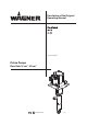
Translation of the Original Operating Manual Version 03/2013 Piston Pumps Flow Rate 15 cm3 - 30 cm3 II 2G IIB c T3 X B_04119
VERSION 03/2013 ORDER NUMBER DOC 2310799 OPERATING MANUAL Contents 1 1.1 1.2 1.3 1.4 ABOUT THIS OPERATING MANUAL Preface Warnings, Notices, and Symbols in this Operating Manual Languages Abbreviations in the Text 5 5 5 6 6 2 2.1 2.2 2.3 2.4 2.5 2.6 2.7 CORRECT USE Device Types Type of Use Use in an Explosion Hazard Area Safety Parameters Processible Materials Reasonably Foreseeable Misuse Residual Risks 7 7 7 7 7 8 8 9 3 3.1 3.
VERSION 03/2013 ORDER NUMBER DOC 2310799 OPERATING MANUAL Contents 6 6.1 6.2 6.3 6.4 6.5 6.5.1 6.5.2 6.5.3 ASSEMBLY AND COMMISSIONING Transportation Storage Assembling the Pump Grounding Commissioning Safety Instructions Filling with Separating Agent Basic Flushing 28 28 28 29 30 32 32 34 35 7 7.1 7.2 7.2.1 7.2.2 7.2.3 7.
VERSION 03/2013 ORDER NUMBER DOC 2310799 OPERATING MANUAL 1 ABOUT THIS OPERATING MANUAL 1.1 PREFACE The operating manual contains information about safely operating, maintaining, cleaning and repairing the device. The operating manual is part of the device and must be available to operating and service staff. Operating and service staff should be instructed according to the safety instructions. The device may only be operated in compliance with this operating manual.
VERSION 03/2013 ORDER NUMBER DOC 2310799 OPERATING MANUAL 1.3 LANGUAGES The operating manual is available in the following languages: Language German French Italian Portuguese Danish 1.4 Order No. 2310798 2310800 2310802 2310804 2310805 Language English Spanish Dutch Swedish Order No. 2310799 2310803 2310801 2310806 ABBREVIATIONS IN THE TEXT Order No. No. Number of pieces Position Marking in the spare parts lists Order No.
VERSION 03/2013 ORDER NUMBER DOC 2310799 OPERATING MANUAL 2 CORRECT USE 2.1 DEVICE TYPES Pneumatic pump with spraypack: 2.2 TYPE OF USE The device is suitable for processing liquid materials such as paints and varnishes in accordance with their classification into explosion classes IIA or IIB. 2.3 USE IN AN EXPLOSION HAZARD AREA The pneumatic pump can be employed in explosion hazard zones (Zone 1). 2.4 SAFETY PARAMETERS WAGNER accepts no liability for any damage arising from incorrect use.
VERSION 03/2013 ORDER NUMBER DOC 2310799 OPERATING MANUAL 2.5 PROCESSIBLE MATERIALS Fluid materials such as paints and varnishes. NOTICE Abrasive materials and pigments! Greater wear of parts carrying the material. Use the application-oriented model (flow rate/cycle, material, valves, etc.) as indicated in Chapter 5.3.2. Check if the fluids and solvents used are compatible with the pump construction materials as indicated in Chapter 5.3.1. 2.
VERSION 03/2013 ORDER NUMBER DOC 2310799 OPERATING MANUAL 2.7 RESIDUAL RISKS Residual risks are risks which cannot be excluded even in the event of correct use. If necessary, warning and prohibition signs at the relevant points of risk indicate residual risks.
VERSION 03/2013 ORDER NUMBER DOC 2310799 OPERATING MANUAL 3 IDENTIFICATION 3.1 EXPLOSION PROTECTION IDENTIFICATION As defined in Directive 94/9/EC (ATEX 95), the device is suitable for use in areas where there is an explosion hazard. European Communities Symbol for explosion protection Device class II Category 2 (Zone 1) Ex-atmosphere gas Explosion group Constructional safety Temperature class: maximum surface temperature < 200 °C; 392 °F Special Notes (see Chapter 3.2) 3.
VERSION 03/2013 ORDER NUMBER DOC 2310799 OPERATING MANUAL 4 GENERAL SAFETY INSTRUCTIONS 4.1 SAFETY INSTRUCTIONS FOR THE OPERATOR Keep this operating manual at hand near the unit at all times. Always follow local regulations concerning occupational safety and accident prevention. 4.1.1 ELECTRICAL EQUIPMENT Electrical devices and equipment To be provided in accordance with the local safety requirements with regard to the operating mode and ambient influences.
VERSION 03/2013 ORDER NUMBER DOC 2310799 OPERATING MANUAL 4.2 SAFETY INSTRUCTIONS FOR STAFF Always follow the information in these instructions, particularly the general safety instructions and the warning instructions. Always follow local regulations concerning occupational safety and accident prevention. 4.2.1 SAFE HANDLING OF WAGNER SPRAY DEVICES The spray jet is under pressure and can cause dangerous injuries. Avoid injection of paint or cleaning agents: Never point the spray gun at people.
VERSION 03/2013 ORDER NUMBER DOC 2310799 OPERATING MANUAL 4.2.2 GROUNDING THE DEVICE In order to avoid electrostatic charging of the device, the device must be grounded. Friction, flowing liquids, and air or electrostatic coating processes create charges. Flames or sparks can form during discharge. Ensure that the device is grounded for every spraying operation. Ground the work pieces to be coated. Ensure that all persons inside the working area are grounded, e.g.
VERSION 03/2013 ORDER NUMBER DOC 2310799 OPERATING MANUAL 4.2.4 CLEANING De-energize the device electrically. Disconnect the pneumatic supply line. Relieve the pressure from the device. Ensure that the flash point of the cleaning agent is at least 5 K above the ambient temperature. To clean, use cloths and brushes moistened with solvent. Never use hard objects or spray on cleaning agents with a gun. Preferably, non-combustible cleaning agents should be used.
VERSION 03/2013 ORDER NUMBER DOC 2310799 OPERATING MANUAL 4.3 USE IN AREAS SUBJECT TO EXPLOSION HAZARDS The pneumatic pump may be used in areas subject to explosion hazards. The following safety regulations must be observed and followed. 4.3.1 SAFETY REGULATIONS Safe handling of WAGNER spray devices Mechanical sparks can form if the device comes into contact with metal. In an explosive atmosphere: Do not knock or push the unit against steel or rusty iron. Do not drop the device.
VERSION 03/2013 ORDER NUMBER DOC 2310799 OPERATING MANUAL 5 DESCRIPTION 5.1 FIELD OF APPLICATION 5.1.1 CORRECT USE The pneumatic piston pump is suitable for conveying and processing (AirCoat technique) liquid materials in accordance with Chapter 5.1.2. 5.1.2 PROCESSIBLE MATERIALS Application Water-based materials Solvent-based materials Low viscosity (<40 sec. DIN No. 4) Medium viscosity (40 to 60 sec. DIN No. 4) High viscosity ( >60 sec. DIN No.
VERSION 03/2013 ORDER NUMBER DOC 2310799 OPERATING MANUAL 5.2 SCOPE OF DELIVERY Pneumatic piston pump consisting of: - Fluid section - Air motor - Connection elements Separating agent 250 ml Conformity certificate GM2000W Operating manual, German Operating manual in the local language Order No.: 9992504 see Chapter 12 Order No.: 2310798 see Chapter 1 The delivery note shows the exact scope of delivery. Accessories: see Chapter 10. 5.3 DATA 5.3.
VERSION 03/2013 ORDER NUMBER DOC 2310799 OPERATING MANUAL 5.3.2 TECHNICAL DATA Description Units Pump ratio Volume flow per double stroke Maximum operating overpressure Maximum possible strokes in operation Minimum/maximum air inlet pressure Ø air inlet connection (inside thread) Minimum Ø of the compressed air supply line Air consumption at 0.
VERSION 03/2013 ORDER NUMBER DOC 2310799 OPERATING MANUAL WARNING Outgoing air containing oil! Risk of poisoning if inhaled. Air motor switching problems. Provide compressed air free from oil and water (Quality Standard 5.5.4 in accordance with ISO 8573.1) 5.5.4 = 40 μm / +7 / 5 mg/m³.
VERSION 03/2013 ORDER NUMBER DOC 2310799 OPERATING MANUAL 5.3.3 MEASUREMENTS AND CONNECTIONS FOR FINEFINISH 40-15 A H1 B L H2 K inch 4.09 4.27 24.45 10.89 5.28 G 1/4" NPS 1/4" M36x2 G 1/4" 8 210 207 86 7 182 80 106 96.5 ø9 ø7 149 ø 25 0.31 8.27 8.15 3.39 0.28 7.17 3.15 4.17 3.8 ø 0.35 ø 0.28 5.87 ø1 I E J mm 104 108.5 621 276.
VERSION 03/2013 ORDER NUMBER DOC 2310799 OPERATING MANUAL 5.3.4 MEASUREMENTS AND CONNECTIONS FOR FINEFINISH 20-30 A H1 B L H2 J inch 4.09 4.27 25.3 7.91 5.3 G 3/8" NPS 1/4" M36x2 G 1/4" 8 210 207 80 7 182 80 106 96.5 ø9 ø7 149 ø 25 0.31 8.27 8.15 3.15 0.28 7.17 3.15 4.17 3.8 ø 0.35 ø 0.28 5.87 ø 0.98 I E K mm 104 108.5 643 201 134.
VERSION 03/2013 ORDER NUMBER DOC 2310799 OPERATING MANUAL PERFORMANCE DIAGRAMS Example Stroke frequency /min Material pressure bar (MPa) psi B AR BAR AR BAR B AR BAR B Air consumption nl/min 5.3.
VERSION 03/2013 ORDER NUMBER DOC 2310799 OPERATING MANUAL Diagram of FineFinish 40-15 Stroke frequency bar (MPa) /min nl/min 300 (30) 10 0 <4350> 20 30 40 50 60 A 240 (24) 240 <8> <3480> 180 180 (18) <6> <2610> C C 120 (12) 120 <4> <1740> 60 (6) 60 <870> <2> 0 0 C_00054 0.15 0.30 0.45 0.60 <0.04> <0.08> <0.12> <0.16> Air consumption B B Material pressure 300 <11> A 0 0.90 l/min 0.75 <0.20> <0.24> Material flow - water A = 8 bar; 0.
VERSION 03/2013 ORDER NUMBER DOC 2310799 OPERATING MANUAL 24
VERSION 03/2013 ORDER NUMBER DOC 2310799 OPERATING MANUAL 5.4 FUNCTION 5.4.
VERSION 03/2013 ORDER NUMBER DOC 2310799 OPERATING MANUAL 5.4.2 1 2 3 4 5 6 7 PRESSURE REGULATOR UNIT Pressure regulator Ball valve Pressure gage (air inlet pressure) Pressure gage for AirCoat air (option) Compressed air inlet Pressure regulator AirCoat (option) Safety and motor pressure relief valve 2 3 1 4 2 6 7 3 1 5 7 5 B_04122 Ball valve positions: 1 2 Open: working position Closed: the air motor may still be under pressure.
VERSION 03/2013 ORDER NUMBER DOC 2310799 OPERATING MANUAL 5.4.3 SAFETY AND MOTOR PRESSURE RELIEF VALVE Safety valve The safety valve (10) has been factory adjusted so as to ensure that if pressure exceeds the permitted operating pressure, the valve, which is held with a spring, automatically opens and releases the excess pressure. As well as handling pressure limits, the valve is also used as a pressure relief valve for the air motor.
VERSION 03/2013 ORDER NUMBER DOC 2310799 OPERATING MANUAL 6 ASSEMBLY AND COMMISSIONING 6.1 TRANSPORTATION The pump can be moved on a trolley or manually without lifting equipment. 6.2 STORAGE Store the pump in a closed and dry environment. Thoroughly clean the pump, if a long-term decommissioning is planned. When resuming pump operation, proceed as described in the following sections.
VERSION 03/2013 ORDER NUMBER DOC 2310799 OPERATING MANUAL 6.3 ASSEMBLING THE PUMP Example: Airless system Notice This pump can be used as part of a spraying system for Airless or AirCoat applications. Individual supplement components for this pump can be found in the Wagner Accessories Catalogue, or can be put together with the Spraypack Configurator. The nozzles must be selected according to the gun instructions.
VERSION 03/2013 ORDER NUMBER DOC 2310799 OPERATING MANUAL 6.4 GROUNDING WARNING Discharge of electrostatically charged components in atmospheres containing solvents! Explosion hazard from electrostatic sparks. Only use a damp cloth to clean the piston pump. WARNING Heavy paint mist if grounding is insufficient! Danger of poisoning. Insufficient paint application quality. Ground all device components. Ground the work pieces to be coated.
VERSION 03/2013 ORDER NUMBER DOC 2310799 OPERATING MANUAL Cable cross sections Pump Paint container Conveyor Spray booth Spraying stand 4 mm2; 6 mm2; 16 mm2; 16 mm2; 16 mm2; Procedure: 1 2 3 4 Screw on grounding cable with eye. Clamp the grounding cable clip to a grounding connection on site. Ground the material (paint) container to an on-site grounding connection. Ground the other parts of the system to an on-site grounding connection.
VERSION 03/2013 ORDER NUMBER DOC 2310799 OPERATING MANUAL 6.5 COMMISSIONING 6.5.1 SAFETY INSTRUCTIONS Before carrying out any work, the following points must be observed in accordance with the operating manual: - Observe all safety regulations in accordance with Chapter 4. - Carry out commissioning properly. WARNING High-pressure spray jet! Danger to life from injecting paint or solvent. Never reach into the spray jet. Never point the spray gun at people.
VERSION 03/2013 ORDER NUMBER DOC 2310799 OPERATING MANUAL Before every start-up, the following points should be observed as laid down in the operating manual: - Check the permissible pressures. - Check all connecting parts for leaks. - Check hoses for damage. It should be ensured that the device is in the following state before carrying out any work on it: - Interrupt the air supply (2). - Depressurize the air motor (pull the ring on the safety valve (10)). - Relieve the pressure from the fluid section.
VERSION 03/2013 ORDER NUMBER DOC 2310799 OPERATING MANUAL 6.5.2 FILLING WITH SEPARATING AGENT NOTICE Piston pump runs dry! High wear/damage to the packings. Paint or solvent can escape if the seals are dry. Ensure that the separating agent container is filled with sufficient separating agent. Filling level 2 cm; 0.8 inch under the cup edge. Pour the supplied separating agent into the intended opening. Filling level: 2 cm; 0.8 inch under the cup edge Separating agent: See accessories.
VERSION 03/2013 ORDER NUMBER DOC 2310799 OPERATING MANUAL 6.5.3 BASIC FLUSHING Before each basic flushing, the nozzle must be removed from the pistol. The data in the gun's operating manual are to be observed. With AirCoat systems, carry out the basic flushing of the system without atomizing air (8). 1 Place empty container (5) under return tube (4). 2 Place suction hose (7) in the container with flushing agent (6). 3 Open return valve (3). 4 Slowly open the ball valve (2).
VERSION 03/2013 ORDER NUMBER DOC 2310799 OPERATING MANUAL 7 7.1 OPERATION FILLING WITH WORKING MATERIAL Note: Before each filling, the nozzle must be removed from the pistol. The data in the gun's operating manual are to be observed. In case of AirCoat systems, carry out the filling of the system without atomizing air (8). 1 2 3 4 5 6 7 8 9 10 11 12 13 Place empty container (5) under return tube (4). Place suction hose (7) in the container with working material (6). Open return valve (3).
VERSION 03/2013 ORDER NUMBER DOC 2310799 OPERATING MANUAL 7.2 WORK 7.2.1 SPRAYING System example for the AirCoat procedure closed 8 1 2 open 9 7 3 4 6 5 B_04080 1 2 3 4 5 6 Secure the gun and insert the nozzle into the gun. Close return valve (3). Slowly open the ball valve (2). Set required working pressure on the pressure regulator (1). Optimize the spraying results according to the data in the gun operating manual. Start work process.
VERSION 03/2013 ORDER NUMBER DOC 2310799 OPERATING MANUAL 7.2.2 PRESSURE RELIEF/WORK INTERRUPTION Pressure relief of the material 1 Close the spray gun. 2 Close ball valve (2). 3 Relieve the system pressure, either by opening the gun or by opening the return valve (3). 4 Close and secure gun. 5 Open and close the return valve (3) to completely depressurize the system. Pressure relief of the air (in case of longer work interruptions) 1 Carry out pressure relief of the material (as mentioned above).
VERSION 03/2013 ORDER NUMBER DOC 2310799 OPERATING MANUAL 7.2.3 DECOMMISSIONING AND CLEANING Notice The device should be cleaned for maintenance purposes. Ensure that no remaining material dries and sticks. Procedure: 1 Carry out pressure relief of the material and air -> Chapter 7.2.2. 2 Basic cleaning -> carry out the steps in Chapter 6.5.3. 3 Maintain the gun according to the operating manual. 4 Clean and check the suction system and the suction filter. 5 Clean the outside of the system.
VERSION 03/2013 ORDER NUMBER DOC 2310799 OPERATING MANUAL 7.3 LONG-TERM STORAGE When storing the device for longer periods of time, it is necessary to thoroughly clean it and protect it from corrosion. For the last rinse, replace the water or solvent in the material pump with a suitable preservative. Fill separating agent cup with separating agent. Store pump vertically. Procedure: 1 Chapter 7.2.3 "Decommissioning and Cleaning", perform points 1 to 7. 2 Flush with preservative according to Chapter 6.5.
VERSION 03/2013 ORDER NUMBER DOC 2310799 OPERATING MANUAL 8 TROUBLESHOOTING AND RECTIFICATION Problem Pump does not work. Cause Air motor does not work or stops. No pressure indication on the pressure gage (air pressure regulator defective). Spray nozzle is clogged. Insufficient compressed air supply. Filter insert in spray gun is clogged. Fluid section or high pressure hose are blocked (e.g., two-component material hardened). Sometimes, the pump stops at a switching point.
VERSION 03/2013 ORDER NUMBER DOC 2310799 OPERATING MANUAL 9 MAINTENANCE WARNING Incorrect maintenance/repair! Danger to life and equipment damage. Only a WAGNER service center or a suitably trained person may carry out repairs and replace parts. Only repair and replace parts that are listed in the "Spare Parts" chapter and that are assigned to the device. Before all work on the device and in the event of work interruptions: - Disconnect the control unit from the mains.
VERSION 03/2013 ORDER NUMBER DOC 2310799 OPERATING MANUAL 9.1 HIGH-PRESSURE HOSES The service life of the fluid hoses is reduced due to environmental influences even when handled correctly. Check hoses, pipes, and couplings every day and replace if necessary. As a precaution, fluid hoses should be replaced after a period specified by the operator. DANGER Bursting hose, bursting threaded joints! Danger to life from injection of material.
VERSION 03/2013 ORDER NUMBER DOC 2310799 OPERATING MANUAL 10 ACCESSORIES Accessories 1 2 3 4 5 Designation Pump PE/T AirCoat regulator set Grounding cable, complete 3 m; 9.8 ft Separating agent 250 ml Separating agent 500 ml Order No. Order No. 2329450 2329452 T6145.00A 236219 9992504 9992505 Material outlet accessories 11 12 13 14 Designation Ball valve R1/4"-G1/4"-PN350-SSt Ball valve R1/4"-G1/4"-PN350-CS Return tube DN6-G1/4"-100mm-PA Return hose DN6-PN310-G1/4"-PA Order No.
VERSION 03/2013 ORDER NUMBER DOC 2310799 OPERATING MANUAL 3 x 2 x 1 11 4/5 12 13 14 18 15 16 17 19 B_04081 45
VERSION 03/2013 ORDER NUMBER DOC 2310799 OPERATING MANUAL Trolley, rack and wall bracket accessories 21 22 23 24 Designation Wall mount 4", complete 4-leg stand Trolley, 4 wheels Trolley 4", complete Order No. 2332143 2332374 T6196.
VERSION 03/2013 ORDER NUMBER DOC 2310799 OPERATING MANUAL 11 SPARE PARTS 11.1 HOW CAN SPARE PARTS BE ORDERED? Always supply the following information to ensure delivery of the right spare part: Order number, designation, and quantity The quantity need not be the same as the number given in the quantity column " " on the lists. This number merely indicates how many of the respective parts are used in each component.
VERSION 03/2013 ORDER NUMBER DOC 2310799 OPERATING MANUAL 11.2 11.2.1 OVERVIEW OF THE COMPONENTS COMPONENTS FOR FINEFINISH 40-15 Designation 1 2 3 4 5 6 7 8 9 10 11 12 13 1 1 1 1 1 2 1 4 4 3 3 1 1 Fluid section 15 PE/T EM Air motor M80 EM D 25 X 160 Spacer Safety fixture spacer Hexagon socket head cap screw Holder plate Washer Hexagon socket head cap screw Hexagon nut with clamp Tie rod Pump air regulator set Screwing in angle Order No. 2329450 2329635 U3B08018060 A359.71A E516.
VERSION 03/2013 ORDER NUMBER DOC 2310799 OPERATING MANUAL 11.2.2 COMPONENTS FOR FINEFINISH 20-30 Designation 1 2 3 4 5 6 7 8 9 10 11 12 13 14 1 1 1 1 1 2 1 4 4 4 4 1 1 1 Fluid section 30 PE/T EM Air motor M80 EM D 25 X 160 Spacer Safety fixture spacer Hexagon socket head cap screw Holder plate Threaded bolt Washer Hexagon extension nut Hexagon socket head cap screw Pump air regulator set Screwing in angle Loctite 222 50ml; 50cc Order No. 2329452 2329639 U3B08018060 A359.71A E516.
VERSION 03/2013 ORDER NUMBER DOC 2310799 OPERATING MANUAL 11.3 AIR MOTOR WARNING Incorrect maintenance/repair! Risk of injury and equipment damage. Have repairs and part replacements carried out only by specially trained staff or a WAGNER service center. Before all work on the device and in the event of work interruptions: - Switch off the energy/compressed air supply. - Relieve the pressure from the spray gun and device. - Secure the spray gun against actuation.
VERSION 03/2013 ORDER NUMBER DOC 2310799 OPERATING MANUAL 30 Nm; 22 lbft 28 2 3 29 4 16 5 35 Nm; 25.8 lbft 6 30 7 29 8 29 9 13 30 4.5 Nm; 3.3 lbft 7 14 29 11 1 10 29 13 3 36 29 35 17 32 33 15 27 31 34 24 19 22 20 Nm; 14.7 lbft 27 29 25 18 23 12 Installation instructions: Mount piston rod (12) always from bottom to top by the assigned rod seal (18).
VERSION 03/2013 ORDER NUMBER DOC 2310799 OPERATING MANUAL Air motor spare parts list EM M80 27 28 29 30 31 32 33 34 35 36 Designation Loctite 542 Hexagon socket head cap screw Mobilux EP 2 grease Loctite 480 Reversing valve ISO N/1 (consisting of items 32 to 36) Reversing valve (spare parts list, see Chapter 11.3.1) Valve plate Valve sealing Washer, A4.3 Hexagon socket head cap screw 1 4 1 1 1 Order No. 9992831 9907241 9998808 9998157 P498.00KNE 1 P498.00 1 1 4 4 A818.71B G735.
VERSION 03/2013 ORDER NUMBER DOC 2310799 OPERATING MANUAL 11.3.1 REVERSING VALVE 4 1 2 3 B_03139 Spare parts list for the reversing valve Designation 1 Reversing valve 2 O-ring Reversing valve gasket 3 Steamer 4 = Wearing part 1 6 1 2 Order No. P498.00 9971123 P521.00 P520.
VERSION 03/2013 ORDER NUMBER DOC 2310799 OPERATING MANUAL 11.4 FLUID SECTIONS 11.4.1 FLUID SECTION 15 30 Nm; 22.1 lbft 24 29 8 36 22 2.5 Nm; 1.
VERSION 03/2013 ORDER NUMBER DOC 2310799 OPERATING MANUAL Spare parts list for fluid section 15 1 2 3 4 5 6 7 8 9 10 11 12 13 14 15 16 17 18 19 20 21 22 23 24 25 26 27 28 29 30 31 32 33 34 35 36 Designation Fluid section 15 SS PE/T EM Connecting flange 15 Snap ring Snap ring flange 15 Packing PE/T 13/25 Spring, upper Tube 15 Spring Packing PE/T 18/29 O-ring Cylinder 15 Piston 15 SS Support spring Ball Valve screw 15 Ball Securing ring Inlet housing 15 Loctite 542 Support ring, outside Support ring, insi
VERSION 03/2013 ORDER NUMBER DOC 2310799 OPERATING MANUAL 11.4.2 FLUID SECTION 30 30 Nm; 22.
VERSION 03/2013 ORDER NUMBER DOC 2310799 OPERATING MANUAL Spare parts list for fluid section 30 1 2 3 4 5 6 7 8 9 10 11 12 13 14 15 16 17 18 19 20 21 22 23 24 25 26 27 28 29 30 31 32 33 34 35 36 37 41 42 43 44 45 Designation Fluid section 30 PE/T, complete Connector Hexagon screw without shaft Connecting flange 30 O-ring Support ring, outside Sealing collar PE 18/29 Sealing collar T 18/29 Support ring, inside Packing PE/T, complete 18/29 Support ring plate Spring O-ring Tube 30 Fitting-DF-MM-R3/8"-1/4"
VERSION 03/2013 ORDER NUMBER DOC 2310799 OPERATING MANUAL 11.5 AIR REGULATOR SET 14 14 9 14 5 14 4 8 1 13 2 14 10 3 11 12 B_04117 Spare parts list for air regulator set Designation 1 Pump air regulator set 2 Hexagon socket head cap screw Pressure gage 0-1 MPa; 0-10 bar; 0-145 psi (d40) 3 4 Reducer 5 Screw-in connection's elbow Ball valve, FM 8 9 Safety valve 1/4" 10 T-connection 11 Straight threaded fitting 12 Hose, black AD8 x 1.25 (0.32 m; 1.
VERSION 03/2013 ORDER NUMBER DOC 2310799 OPERATING MANUAL 11.6 AIR REGULATOR SET FOR AIRCOAT AIR 7 6 4 7 5 1 3 7 B_03436 2 Spare parts list for air regulator set for AirCoat Air Designation 1 AirCoat regulator set 2 Pressure gage 0-1 MPa; 0-10 bar; 0-145 psi (d40) 3 Elbow with taper 4 Detachable double nipple 5 T-piece Air pressure regulator, 1/4" 6 7 Loctite 270 = Wearing part 1 1 1 1 1 1 1 Order No. T6145.00A 9998677 9992129 9998719 9985694 P123.
VERSION 03/2013 ORDER NUMBER DOC 2310799 OPERATING MANUAL 11.
VERSION 03/2013 ORDER NUMBER DOC 2310799 OPERATING MANUAL 11.8 4-WHEEL TROLLEY 4 12 3 2 8 13 5 1 6 10 9 11 7 B_03439 Designation 1 Trolley, 4 wheels 2 Hexagon nut with clamp 3 Stand, right 4 Stand, left 5 Spray gun hook 6 Stand pin 7 Plug 8 Contact washer, M08 9 Washer Wheel 10 11 Hexagon socket head cap screw 12 Hexagon socket head cap screw 13 Hexagon socket head cap screw 14 Hexagon nut with clamp = Wearing part 14 1 5 1 1 1 1 4 4 4 4 4 4 2 4 Order No. T6196.00 9910204 E3107.92B E3107.
VERSION 03/2013 ORDER NUMBER DOC 2310799 OPERATING MANUAL 12 12.1 3+2 YEARS GUARANTEE FOR PROFESSIONAL FINISHING SCOPE OF GUARANTEE All Wagner professional colour application devices (hereafter referred to as products) are carefully inspected, tested, and subject to strict checks under Wagner quality assurance.
VERSION 03/2013 ORDER NUMBER DOC 2310799 OPERATING MANUAL 12.4 EXCLUSION OF GUARANTEE Guarantee claims cannot be considered - for parts that are subject to wear and tear due to use or other natural wear and tear, as well as defects in the product that are a result of natural wear and tear, or wear and tear due to use. This includes in particular cables, valves, packings, nozzles, cylinders, pistons, means-carrying housing components, filters, pipes, seals, rotors, stators, etc.
VERSION 03/2013 ORDER NUMBER DOC 2310799 OPERATING MANUAL 64
VERSION 03/2013 ORDER NUMBER DOC 2310799 OPERATING MANUAL 12.6 CE DECLARATION OF CONFORMITY Herewith we declare that the supplied version of pneumatic pumps and their spraypacks FineFinish comply with the following guidelines: 2006/42/EC 94/9/EC Applied standards, in particular: Applied national technical standards and specifications, in particular: Part 2 Chapter 2.29 and Chapter 2.
VERSION 03/2013 ORDER NUMBER DOC 2310799 OPERATING MANUAL 66
ED FI CERT A I DK Tel. Fax B GB Tel. Fax E Tel. Fax CH I Tel. Fax F Tel. Fax D Tel. Fax NL Tel. Fax Tel. Fax CZ S Tel. Fax Tel. +49 / 75 44 / 505 -1664 Fax Fax Tel. Fax Subject to changes and errors.