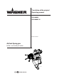
Translation of the original Operating manual GM 4600AC GM 4600AC-H Edition 04/2009 AirCoat Spray gun for flat - and round jet nozzles B_02669 II 2G X (Atex 95)
EDITION 04/2009 Part No. DOC394861 GM 4600AC OPERATING MANUAL Contents 1 1.1 1.2 ABOUT THESE INSTRUCTIONS Languages Warnings, notes and symbols in these instructions 5 5 5 2 2.1 2.1.1 2.1.2 2.1.3 2.2 2.2.1 2.2.2 2.2.3 2.2.4 2.2.5 2.2.6 2.3 2.4 2.4.1 2.4.2 2.4.3 2.4.4 2.
EDITION 04/2009 Part No. DOC394861 GM 4600AC OPERATING MANUAL Contents 5.1.5 5.2 5.3 5.3.1 5.3.2 5.4 5.4.1 5.4.2 5.4.3 5.4.4 5.4.5 Earthing Preparation of paints Start-up General rules for handling the spray gun Preparation for starting up Works Start-up for spraying AirCoat Adjusting the spray pattern Replacing AirCoat nozzle Cleaning aircoat nozzle Eliminate nozzle clogging 18 18 19 19 20 21 21 21 22 23 23 6.0 6.1 6.2 6.3 6.4 6.4.1 6.4.2 6.4.3 6.4.4 6.5 6.
EDITION 04/2009 GM 4600AC Part No. DOC394861 OPERATING MANUAL 1 ABOUT THESE INSTRUCTIONS 4HIS OPERATING MANUAL CONTAINS INFORMATION ON THE OPERATION REPAIR AND MAINTENANCE OF THE UNIT !LWAYS OBSERVE THESE INSTRUCTIONS WHEN OPERATING THE UNIT 4HIS EQUIPMENT CAN BE DANGEROUS IF IT IS NOT OPERATED IN ACCORDANCE WITH THIS MANUAL #OMPLIANCE WITH THESE INSTRUCTIONS CONSTITUTES AN INTEGRAL COMPONENT OF THE WARRANTY AGREEMENT 1.
EDITION 04/2009 Part No. DOC394861 GM 4600AC OPERATING MANUAL 2 GENERAL SAFETY INSTRUCTIONS 2.1 SAFETY INSTRUCTIONS FOR THE OPERATOR +EEP THESE OPERATING INSTRUCTIONS TO HAND NEAR THE UNIT AT ALL TIMES !LWAYS FOLLOW LOCAL REGULATIONS CONCERNING OCCUPATIONAL SAFETY AND ACCIDENT PREVEN TION 2.1.
EDITION 04/2009 Part No. DOC394861 GM 4600AC OPERATING MANUAL 2.2.1 SAFE HANDLING OF WAGNER SPRAY UNITS The spray jet is under pressure and can cause dangerous injuries. Avoid injection of paint or cleaning agents: Never point the spray gun at people. Never reach into the spray jet. Before all work on the unit, in the event of work interruptions and functional faults: – Switch off the energy/compressed air supply. – Secure the spray gun against actuation.
EDITION 04/2009 Part No. DOC394861 GM 4600AC OPERATING MANUAL 2.2.4 CLEANING $E ENERGIZE THE UNIT ELECTRICALLY $ISCONNECT THE PNEUMATIC SUPPLY LINE 2ELIEVE THE PRESSURE FROM THE UNIT %NSURE THAT THE mASH POINT OF THE CLEANING AGENT IS AT LEAST + ABOVE THE AMBIENT TEM PERATURE 4O CLEAN USE ONLY SOLVENT FREE CLOTHS AND BRUSHES .
EDITION 04/2009 Part No. DOC394861 GM 4600AC OPERATING MANUAL 2.4 USE IN HAZARDOUS LOCATIONS 2.4.1 CORRECT USE 4HE UNIT IS SUITABLE FOR WORKING LIQUID MATERIALS IN ACCORDANCE WITH THE CLASSIlCATION INTO EXPLOSION CLASSES 2.4.2 EXPLOSION PROTECTION IDENTIFICATION As defined in the Directive 94/9/CE (ATEX 95), the unit is suitable for use in areas where there is an explosion hazard.
EDITION 04/2009 Part No. DOC394861 GM 4600AC OPERATING MANUAL 3 GUARANTEE AND CONFORMITY DECLARATIONS 3.
EDITION 04/2009 Part No. DOC394861 GM 4600AC OPERATING MANUAL 3.
EDITION 04/2009 Part No. DOC394861 GM 4600AC OPERATING MANUAL 4 DESCRIPTION 4.1 FIELDS OF APPLICATION, USING IN ACCORDANCE WITH THE INSTRUCTIONS The gun is suitable for atomising liquid materials, particularly coating materials, using the AirCoat process. 4.1.1 PROCESSIBLE MATERIALS Top-coat paints, primer paints, corrosion protection solvents, textured paints, lyes, staining solvents, clear paints, parting solvents, etc. on a solvent or water basis.
EDITION 04/2009 GM 4600AC Part No. DOC394861 OPERATING MANUAL 4.2.4 SPRAY GUN CONFIGURATION A B CCC B_02670 Basis number GM 4600AC 0 3 9 4 0 2 0 - A B C C C -> Key - 1 1 4 1 1 -> For example: Part number Table A: Maxi.
EDITION 04/2009 GM 4600AC Part No. DOC394861 OPERATING MANUAL 4.3 DATA 4.3.1 MATERIALS OF THE PARTS TRANSPORTING PAINT Metal Plastics Tungsten carbide Stainless steel 1.4305 POM FPM Stainless steel 1.4301 Stainless steel 1.4104 PTFE PA 4.3.2 TECHNICAL DATA AirCoat spray gun Description Units 394004 394014; 2303491 Maxi. air pressure MPa/ psi/ bar 0.8/ 120/ 8 Maxi.
EDITION 04/2009 GM 4600AC Part No. DOC394861 OPERATING MANUAL 4.4 FUNCTIONAL DESCRIPTION 4.4.1 DESIGN OF SPRAY GUN B C A J I E D H K F B_02672 G Description A Suspension hook B Fan air regulator C Tension nut D Trigger E Trigger safety F Air connection G Paint connection H Union nut with nozzle guard I Nozzle / Air cap J Gun housing K Filter housing 4.4.
EDITION 04/2009 GM 4600AC Part No. DOC394861 OPERATING MANUAL 5 STARTING UP AND OPERATING 5.1 INSTALLATION AND CONNECTION 5.1.1 TYPICAL AIRCOAT SPRAYING SYSTEM WARNING Incorrect installation/operation! Risk of injury and damage to equipment When putting into operation and for all work, read and follow the operating instructions and safety regulations for the additionally required system components.
EDITION 04/2009 Part No. DOC394861 GM 4600AC OPERATING MANUAL 5.1.2 VENTILATION OF THE SPRAY BOOTH WARNING Toxic and/or flammable vapor mixtures! Risk of poisoning and burns Operate the unit in a spraying booth approved for the working materials. -or Operate the unit on an appropriate spraying wall with the ventilation (extraction) switched on. Observe national and local regulations for the outgoing air speed. SIHI_0028_GB 5.1.
EDITION 04/2009 Part No. DOC394861 GM 4600AC OPERATING MANUAL 5.1.5 EARTHING WARNING Discharge of electrostatically charged components in atmospheres containing solvents! Explosion hazard from electrostatic sparks or flames Earth all unit components. Earth the workpieces being painted. SIHI_0027_GB WARNING Heavy paint mist if earthing is insufficient! Risk of poisoning Insufficient paint application quality Earth all unit components. Earth the workpieces being painted.
EDITION 04/2009 Part No. DOC394861 GM 4600AC OPERATING MANUAL 5.3 START-UP 5.3.1 GENERAL RULES FOR HANDLING THE SPRAY GUN ➞ Observe general safety instructions in chapter 2. WARNING Unintentional putting into operation! Risk of injury Before all work on the unit, in the event of work interruptions and functional faults: Switch off the energy/compressed air supply. Relieve the pressure from the spray gun and unit. Secure the spray gun against actuation.
EDITION 04/2009 Part No. DOC394861 GM 4600AC OPERATING MANUAL 5.3.2 PREPARATION FOR STARTING UP 1. 2. 3. 4. 5. Secure the spray gun. Connect material hose to the spray gun and material supply system. Connect air hose to spray gun and to oil-free, dry air supply with regulator. Insert suitable gun filter Place the nozzle into the nozzle seal. Fit the air cap over the nozzle, ensuring that the location flats (X) are in line. Fit the union nut with nozzle guard and tighten by hand. 6.
EDITION 04/2009 Part No. DOC394861 GM 4600AC OPERATING MANUAL 5.4 WORKS 5.4.1 START-UP FOR SPRAYING AIRCOAT 1. Start up with material supply set to approx. 8 MPa; 80 bar; 1160 psi operating pressure. 2. Spray (release trigger safety catch and pull trigger) and check the atomisation. 3. Set the fluid pressure to the point where a further increase in fluid pressure would significantly improve fluid atomization. 4.
EDITION 04/2009 GM 4600AC Part No. DOC394861 OPERATING MANUAL 5.4.3 REPLACING AIRCOAT NOZZLE CAUTION Defective AirCoat nozzle! Insufficient paint application quality Do not use sharp-edged objects to treat hard metal on the AirCoat nozzle. SIHI_0020_GB 1. 2. 3. 4. 5. Relieve spray gun and unit pressure. Secure gun with trigger safety catch. Screw off the union nut (A). Remove air cap (B).
EDITION 04/2009 GM 4600AC Part No. DOC394861 OPERATING MANUAL 5.4.4 CLEANING AIRCOAT NOZZLE For disassembly and assembly of AirCoat nozzles see chapter 5.4.3. The AirCoat nozzle (C) can be placed into a cleaning solvent which has been recommended by the paint manufacturer. 5.4.5 1. 2. 3. 4. 5. 6. 7. 8. 9. 10. 11. 12. 13. 14. 15. 16. ELIMINATE NOZZLE CLOGGING Relieve spray gun and unit pressure. Secure gun with trigger safety catch. Unscrew the union nut with nozzle guard (A). Remove air cap (B).
EDITION 04/2009 Part No. DOC394861 GM 4600AC OPERATING MANUAL 6.0 MAINTENANCE ➞ Observe general safety instructions in chapter 2. The spray gun and the unit must be cleaned every day. Use only the cleaning solvent recommended by the material manufacture. CAUTION Cleaning agent in the air duct! Functional faults caused by swollen seals Never immerse the spray gun in cleaning agent.
EDITION 04/2009 Part No. DOC394861 GM 4600AC OPERATING MANUAL 6.1 FINISHING WORK AND CLEANING DANGER Exploding gas/ air mixture! Danger to life from flying parts and burns Never spray into a closed container. Earth the container. SIHI_0008_GB CAUTION Cleaning agent in the air duct! Functional faults caused by swollen seals Always point the spray gun down when cleaning. Ensure that neither paint nor cleaning agent enters the air duct.
EDITION 04/2009 GM 4600AC Part No. DOC394861 OPERATING MANUAL 6.2 REPLACING THE MATERIAL HOSE OR AIR HOSE 1. Finishing work and cleaning. 2. Relieve spray gun and unit pressure. 3. Secure gun with trigger safety catch. Paint hose 4. Place open-ended wrench SW A on flats of paint connection and counter hold. 5. Turn nut to the right with open-ended wrench SW D and unscrew material hose. Air hose 4. Place open-ended wrench SW D on flats of air connection and counter hold. 5.
EDITION 04/2009 GM 4600AC Part No. DOC394861 OPERATING MANUAL 6.3 1. 2. 3. 4. 5. 6. 7. 8. 9. CHANGING OR CLEANING FILTER INSERT Finishing work and cleaning. Relieve spray gun and unit pressure. Secure gun with trigger safety catch. Place open-ended wrench A on flats of filter housing (30) and counter hold. Turn nut to the right with open-ended wrench B and unscrew pivot joint (67) with material hose. Remove the filter insert (64), seal (65) and compression spring (66).
EDITION 04/2009 GM 4600AC Part No. DOC394861 OPERATING MANUAL 6.4 REPLACING PARTS ON THE VALVE ROD 6.4.1 1. 2. 3. 4. 5. 6. 7. DISASSEMBLING Finishing work and cleaning. Relieve spray gun and unit pressure. Secure gun with trigger safety catch. Unscrew spring cover (5) and remove compression springs (2) and (3). Loosen screw (22) and remove together with nut (20). Remove trigger (21). Loosen sealing screw (10) with single open-end wrench SW 7 mm; 0.28 inches.
EDITION 04/2009 GM 4600AC Part No. DOC394861 OPERATING MANUAL 6.4.2 REPLACEMENT OF VALVE ROCKER SEALS 1. Support valve tappet (50) with single open-end wrench SW 13 mm; 0.51 inches and unscrew cover (53) with single open-end wrench SW 7 mm; 0.28 inches. 2. Remove air valve seal (51) and seal (52) and replace with new seals. 3. Screw valve tappet (50) and cover (53) together by hand. Carefully tighten in small increments with open-end wrench SW 7 mm; 0.28 inches and SW 13 mm; 0.
EDITION 04/2009 GM 4600AC Part No. DOC394861 OPERATING MANUAL 6.5 REPLACING THE NOZZLE SEAL CAUTION Defective nozzle seal! Material sprays into the air cap next to the nozzle Risk of contamination Do not clean the nozzle seal with sharp-edged objects. Replace the nozzle seal if the sealing surface is damaged. SIHI_0021_GB 1. 2. 3. 4. 5. 6. 7. 8. Finishing work and cleaning. Relieve spray gun and unit pressure. Secure gun with trigger safety catch. Unscrew the union nut with nozzle guard (33).
EDITION 04/2009 GM 4600AC Part No. DOC394861 OPERATING MANUAL 6.6 REPLACING THE „AIR“ SEALING RING CAUTION Forming air and atomizer air not separate! Poor spray pattern Spray jet cannot be adjusted Treat the distributor seal (F) with care. SIHI_0030_GB 1. 2. 3. 4. 5. 6. 7. 8. 9. 10. Finishing work and cleaning. Relieve spray gun and unit pressure. Secure gun with trigger safety catch. Unscrew the union nut with nozzle guard (33). Remove air cap (36) and nozzle (13) .
EDITION 04/2009 GM 4600AC Part No.
EDITION 04/2009 GM 4600AC Part No. DOC394861 OPERATING MANUAL 9 ACCESSORIES 9.1 ROUND-JET NOZZLE CAP 9.1 Part No. Description 394180 Round-jet nozzle cap (without nozzle insert) 9.1.2 B_02276 9.1.1 9.1.1 NOZZLE INSERTS RXX Part No. Description Marking Volume flow* Jet ø ** 132720 Nozzle insert R11 11 0.16; 160 approx. 250; 9.84 132721 Nozzle insert R12 12 0.22; 220 approx. 250; 9.84 132722 Nozzle insert R13 13 0.27; 270 approx. 250; 9.84 132723 Nozzle insert R14 14 0.
EDITION 04/2009 GM 4600AC Part No. DOC394861 OPERATING MANUAL 9.2 AIRCOAT NOZZLES ACF3000 B_02280 Size mm; inch Spraying angle 379107 07/10 0.007-0.18 100 379207 07/20 0.007-0.18 200 379209 09/20 0.009-0.23 200 0 379309 09/30 0.009-0.23 30 379409 09/40 0.009-0.23 400 379509 09/50 0.009-0.23 500 379609 09/60 0.009-0.23 600 379111 11/10 0.011-0.28 100 379211 11/20 0.011-0.28 200 379311 11/30 0.011-0.28 300 379411 11/40 0.011-0.28 400 379511 11/50 0.011-0.
EDITION 04/2009 GM 4600AC Part No. DOC394861 OPERATING MANUAL B_02280 19/20 0.019-0.48 Recommended gunfilter Application yellow (100 Meshes) 379219 Marking Spraying angle 0 20 0 379319 19/30 0.019-0.48 30 379419 19/40 0.019-0.48 400 379519 19/50 0.019-0.48 500 379619 19/60 0.019-0.48 600 379819 19/80 0.019-0.48 800 379221 21/20 0.021-0.53 200 379421 21/40 0.021-0.53 400 379521 21/50 0.021-0.53 500 379621 21/60 0.021-0.53 600 379821 21/80 0.021-0.
EDITION 04/2009 GM 4600AC Part No. DOC394861 OPERATING MANUAL 9.3 AIR CAPS Part No. Description 394910 Air cap LV complete (red) for low viscosity paints 394911 Air cap HV complete (blue) for high viscosity paints B_02257 B_02256 9.4 FILTER INSERT Part No. for 1 piece Part No. Filter types for 10 piece 34383 97022 Gun filter red Mesh Use for nozzles 200 0.007“ - 0.015“ "? 43235 97023 Gun filter yellow 100 0.015“ - 0.019“ "? 34377 9.5 97024 Gun filter white 50 0.
EDITION 04/2009 Part No. DOC394861 GM 4600AC OPERATING MANUAL 9.6 HOSES Part No. Description 394100 Hose set AC Material DN3; Air DN6 Consisting of paint- air- and protective hose. Material: NPSM1/4“; 7.5 m; 24.6 ft; DN 3 mm; ID 0.12 inch; 27 MPa; 270 bar; 3916 psi Air: G1/4“; 7.5 m; 24.6 ft; DN 6 mm; ID 0.24 inch; 0.8 MPa; 8 bar; 116 psi 394101 Hose set AC Material DN4; Air DN6 Consisting of paint- air- and protective hose. Material: NPSM1/4“; 7.5 m; 24.6 ft; DN 4 mm; ID 0.
EDITION 04/2009 Part No. DOC394861 GM 4600AC OPERATING MANUAL 10 SPARE PARTS 10.1 HOW TO ORDER SPARE PARTS? !LWAYS SUPPLY THE FOLLOWING INFORMATION TO ENSURE DELIVERY OF THE RIGHT SPARE PART 0ART .
EDITION 04/2009 Part No. DOC394861 GM 4600AC OPERATING MANUAL 10.2 SPARE PARTS LIST GM 4600AC Spare parts list GM 4600AC 16 MPa Part No. Pos K Qty 1 1 394004 2 1 9999501 25 MPa Part No. 3940014 Description GM 4600AC; XX MPa; NPSM1/4“ 9999501 Screw spring Material 3 1 9999500 9999500 Screw spring Air 4 1 394256 394256 Tension sleeve compl. 5 1 394335 - Spring cap 16 MPa; 160 bar: 2320 psi 5 1 - 394333 Spring cap 25 MPa; 250 bar: 3625 psi 6 1 394924 394924 Air tappet assy.
EDITION 04/2009 GM 4600AC Part No. DOC394861 OPERATING MANUAL GM 4600AC 5 55 62 56 1 57 58 59 60 80 6 61 63 2 3 5 8 82 B 14 20 21 22 36 15 16 23 13 35 17 24 36 64 84 B_02748 Detail B 83 65 66 4 67 18 Mounting materials 19 10 82 50 51 52 53 11 12 34 Pos K Part No.
EDITION 04/2009 Part No. DOC394861 GM 4600AC OPERATING MANUAL Spare parts list GM 4600AC 16 MPa Part No. Pos K Qty 56 1 128327 ◆● 57 1 132516 ◆● 58 1 132351 ● 59 1 394308 ● 60 1 394337 ● 61 1 132... ◆● 25 MPa Part No. 128327 132516 132351 394308 394337 132... 62 ● 1 394180 394180 63 64 ◆● ◆ 1 1 132922 43235 132922 43235 65 ✭ 66 ✭ ◆ 1 128389 128389 Description Sealing nipple Nozzle screwed connection compl.
EDITION 04/2009 Part No. DOC394861 GM 4600AC OPERATING MANUAL 10.3 SPARE PARTS LIST GM 4600AC-H Spare parts list GM 4600AC-H Pos K Qty 25 MPa Description Part No. 1 1 2303491 GM 4600AC-H; 25MPa; NPSM1/4“ 2 1 9999501 Screw spring Material 3 1 9999500 Screw spring Air 4 1 394256 Tension sleeve compl. 5 1 394333 Spring cap 25 MPa; 250 bar: 3625 psi 6 ◆ 1 394924 Air tappet assy. 8 ◆ 1 2311320 Valve rod unit assy.
EDITION 04/2009 GM 4600AC Part No. DOC394861 OPERATING MANUAL GM 4600AC-H 62 55 56 1 5 57 58 59 60 80 6 61 63 2 3 70 8 69 B 82 14 20 21 22 36 15 16 23 13 35 17 24 36 64 84 B_02880 83 65 66 4 67 18 Mounting materials 19 10 82 50 51 52 53 11 12 34 Pos K Part No.
EDITION 04/2009 Part No. DOC394861 GM 4600AC OPERATING MANUAL Spare parts list GM 4600AC-H Pos K Qty 25 MPa Description 56 ◆ ● 1 128327 Sealing nipple 57 ◆ ● 1 132516 Nozzle screwed connection compl. 58 ● 1 132351 Nozzle screwed connection holder 59 ● 1 394308 Union nut 60 ● 1 394337 Nozzle nut 61 ◆ ● 1 132... 62 ● 1 394180 Round-jet nozzle cap (see chapter 9.1) 63 ◆ ● 1 132922 Nozzle screwed connection compl.
EDITION 04/2009 Part No.
EDITION 04/2009 Part No. DOC394861 GM 4600AC OPERATING MANUAL Germany J. WAGNER GmbH Otto-Lilienthal-Str. 18 Postfach 1120 D- 88677 Markdorf Telephone: +49 7544 5050 Telefax: +49 7544 505200 E-Mail: service.standard@wagner-group.com Switzerland J. WAGNER AG Industriestrasse 22 Postfach 663 CH- 9450 Altstätten Telephone: +41 (0)71 757 2211 Telefax: +41 (0)71 757 2222 E-Mail: rep-ch@wagner-group.
ED FI CERT I /RDER NUMBER 394861 'ERMANY * 7!'.%2 'MB( /TTO ,ILIENTHAL 3TR 0OSTFACH $ -ARKDORF 4ELEPHONE 4ELEFAX % -AIL SERVICE STANDARD WAGNER GROUP COM 3WITZERLAND * 7!'.