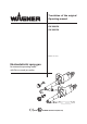
Translation of the original Operating manual GA 2800EA GA 2805EA Edition 12/2008 Electrostatic Air spray gun for automatic operating mode with flat or round jet nozzles "? 0102 II 2G EEx 0.
EDITION 12/2008 PART NO. DOC350731 GA 2800EA, GA 2805EA OPERATING MANUAL Contents 1 1.1 1.2 ABOUT THESE INSTRUCTIONS Languages Warnings, notes and symbols in these instructions 5 5 5 2 2.1 2.1.1 2.1.2 2.1.3 2.2 2.2.1 2.2.2 2.2.3 2.2.4 2.2.5 2.2.6 2.3 2.4 2.5 2.5.1 2.5.2 2.5.3 2.5.4 2.6 2.
EDITION 12/2008 PART NO. DOC350731 GA 2800EA, GA 2805EA OPERATING MANUAL Contents 5.1.3 5.1.4 5.1.5 5.2 5.2.1 5.3 5.3.1 5.3.2 5.4 5.4.1 5.4.2 5.4.3 5.4.4 5.4.
EDITION 12/2008 GA 2800EA, GA 2805EA PART NO.
EDITION 12/2008 PART NO. DOC350731 GA 2800EA, GA 2805EA OPERATING MANUAL 2 GENERAL SAFETY INSTRUCTIONS 2.1 SAFETY INSTRUCTIONS FOR THE OPERATOR +EEP THESE OPERATING INSTRUCTIONS TO HAND NEAR THE UNIT AT ALL TIMES !LWAYS FOLLOW LOCAL REGULATIONS CONCERNING OCCUPATIONAL SAFETY AND ACCIDENT PREVEN TION 2.1.
EDITION 12/2008 PART NO. DOC350731 GA 2800EA, GA 2805EA OPERATING MANUAL 2.2.1 SAFE HANDLING OF WAGNER SPRAY UNITS The spray jet is under pressure and can cause dangerous injuries. Avoid injection of paint or cleaning agents: Never point the spray gun at people. Never reach into the spray jet. Before all work on the unit, in the event of work interruptions and functional faults: – Switch off the energy/compressed air supply. – Secure the spray gun against actuation.
EDITION 12/2008 PART NO. DOC350731 GA 2800EA, GA 2805EA OPERATING MANUAL 2.2.4 CLEANING $E ENERGIZE THE UNIT ELECTRICALLY $ISCONNECT THE PNEUMATIC SUPPLY LINE 2ELIEVE THE PRESSURE FROM THE UNIT %NSURE THAT THE mASH POINT OF THE CLEANING AGENT IS AT LEAST + ABOVE THE AMBIENT TEM PERATURE 4O CLEAN USE ONLY SOLVENT FREE CLOTHS AND BRUSHES .
EDITION 12/2008 PART NO. DOC350731 GA 2800EA, GA 2805EA OPERATING MANUAL 2.4 SAFETY-RELEVANT INFORMATION ABOUT DISCHARGES The plastic parts of the spray gun are charged electrostatically by the high-voltage field of the spray pistol. Harmless discharges (brush discharges) are possible after contact with plastic parts. They are completely harmless for people. The corona discharge at the electrode end is visible during darkness at a distance of between 4 and 10 mm; 0.15 and 0.
EDITION 12/2008 PART NO.
EDITION 12/2008 PART NO. DOC350731 GA 2800EA, GA 2805EA OPERATING MANUAL 3 PRODUCT LIABILITY AND WARRANTY 3.
EDITION 12/2008 GA 2800EA, GA 2805EA PART NO. DOC350731 OPERATING MANUAL 3.
EDITION 12/2008 PART NO. DOC350731 GA 2800EA, GA 2805EA OPERATING MANUAL 3.
EDITION 12/2008 PART NO. DOC350731 GA 2800EA, GA 2805EA OPERATING MANUAL 4 DESCRIPTION 4.1 AREA OF APPLICATION, USING IN ACCORDANCE WITH THE INSTRUCTIONS The electrostatic spray guns can only be used with the control units designed for that purpose: Part No.
EDITION 12/2008 PART NO. DOC350731 GA 2800EA, GA 2805EA OPERATING MANUAL 4.2 SCOPE OF SUPPLY Qty Part No.
EDITION 12/2008 GA 2800EA, GA 2805EA PART NO. DOC350731 OPERATING MANUAL 4.3 TECHNICAL DATA Maxi. air pressure Maxi. atomizing air pressure Maxi. material pressure Input voltage Input current Output voltage Output current Polarity Maxi. discharge energy (accord. EN 50176 classification for type A) Material hose connection Length material hose Atomizing air connection Fan air connection Control air connection Cable length Weight (without cables) Working temperature range Maxi. temperature material Min.
EDITION 12/2008 GA 2800EA, GA 2805EA PART NO. DOC350731 OPERATING MANUAL 4.4 FUNCTION 4.4.
EDITION 12/2008 GA 2800EA, GA 2805EA PART NO. DOC350731 OPERATING MANUAL 4.5 AIR ATOMIZING SPRAY PROCESS 4.5.1 ROUND AND FLAT JET In this process, the material (paint) is fed to the nozzle with low pressure 0.05-0.2 MPa; 0.52 bar; 7-29 psi. The atomizing air at approx. 0.25-0.4 MPa; 2.5-4 bar; 36-58 psi produces a soft jet, which largely eliminates the problem of overlapping boundaries. 4.5.2 ROUND JET The jet is cone-shaped. Spray pattern "? 1 = Atomizing air 4.5.
EDITION 12/2008 PART NO. DOC350731 GA 2800EA, GA 2805EA OPERATING MANUAL 4.5.4 ELECTROSTATIC EFFECT The spray gun produces an electrostatic field by means of the high voltage electrode. As a result, the particles of paint, which have been atomized by the spray gun, are carried to the earthed object by kinetic and electrostatic energy where they adhere, finely distributed, to the object being sprayed.
EDITION 12/2008 GA 2800EA, GA 2805EA PART NO. DOC350731 OPERATING MANUAL 5 PREPARATION BEFORE STARTING WORK 5.1 SET UP AND CONNECT 5.1.1 TYPICAL ELECTROSTATIC SPRAYING SYSTEM WARNING Incorrect installation/operation! Risk of injury and damage to equipment When putting into operation and for all work, read and follow the operating instructions and safety regulations for the additionally required system components.
EDITION 12/2008 PART NO. DOC350731 GA 2800EA, GA 2805EA OPERATING MANUAL 5.1.2 VENTILATION OF THE SPRAY BOOTH WARNING Toxic and/or flammable vapor mixtures! Risk of poisoning and burns Operate the unit in a spraying booth approved for the working materials. -or Operate the unit on an appropriate spraying wall with the ventilation (extraction) switched on. Observe national and local regulations for the outgoing air speed. SIHI_0028_GB 5.1.
EDITION 12/2008 PART NO. DOC350731 GA 2800EA, GA 2805EA OPERATING MANUAL 5.1.5 EARTHING Perfect earthing of all system components (work pieces, conveyor, paint supply system, control unit, spray booth or spraying stand, see illustration) is a prerequisite for optimum coating efficiency and safety. 7!2.).
EDITION 12/2008 PART NO.
EDITION 12/2008 GA 2800EA, GA 2805EA PART NO. DOC350731 OPERATING MANUAL 5.2 PREPARATION OF PAINT The viscosity of the paints is of great importance. The best results are obtained with paints between 15 and 30 DIN sec. (measured in immersion flow cup DIN 4 mm ; 0.16 inches). In the case of application problems contact the paint producer. 5.2.1 VISCOSITY CONVERSION TABLE MILLI 0ASCAL X 3EC M0AS #ENTIPOISE 0OISE $).
EDITION 12/2008 PART NO. DOC350731 GA 2800EA, GA 2805EA OPERATING MANUAL 5.3 START-UP 5.3.1 GENERAL RULES FOR HANDLING THE SPRAY GUN ➞ Observe safety instructions in chapter 2. DANGER High voltage field! Danger to life from malfunctioning heart pacemakers Ensure that persons with heart pacemakers: Do not work with the electrostatic spray gun. Remain outside the area of the electrostatic spray gun/workpiece.
EDITION 12/2008 PART NO. DOC350731 GA 2800EA, GA 2805EA OPERATING MANUAL 5.3.2 PREPARATION ➞ Earthing the spraying system and make sure that all other conductive parts within the work area are earthed. ➞ Secure the spray gun to the lifting unit with the suspension bracket or suspension bolt (accessories) ➞ Connect material hose to pump. ➞ Connect the air hose ø 10 mm; ø 0.39 inches (marked blue) to oil-free, dry air supply (approx 0.25 MPa; 2.5 bar; 36.3 psi with regulator.
EDITION 12/2008 GA 2800EA, GA 2805EA PART NO. DOC350731 OPERATING MANUAL 5.4 WORKING 5.4.1 START-UP FOR SPRAYING 1. Switch on the material supply, adjust from approx. 0.05-0.15 MPa; 0.5-1.5 bar; 7-22 psi, and the control unit. 2. Spray on a test object. 3. Adjust the spray pressure and atomizing air in accordance with the nozzle and object. Note The paint output volume can be changed by: ➞ Changing the material pressure. or ➞ Fitting another flat. See accessories. 5.4.
EDITION 12/2008 GA 2800EA, GA 2805EA PART NO. DOC350731 OPERATING MANUAL 5.4.3 FITTING OR CHANGING ROUND JET NOZZLE 1. 2. 3. 4. 5. 6. Switch off control unit. Relieve spray gun and unit pressure! Replace paint with cleaning solvent, and Thoroughly flush spray gun. Relieve spray gun and unit pressure! Unscrew nozzle nut (B) by hand and remove it. 7. Remove the nozzle body (C) and the nozzle insert Supra (A). 8. Unscrew nozzle insert Supra (A) with the nozzle spanner (I) from the nozzle body (C) 9.
EDITION 12/2008 GA 2800EA, GA 2805EA PART NO. DOC350731 OPERATING MANUAL 5.4.4 CHANGING FROM ROUND JET NOZZLE TO FLAT JET NOZZLE #!54)/. $EFECTIVE ELECTRODE -ATERIAL DAMAGE DUE TO FUNCTIONAL FAULTS $O NOT DAMAGE THE ELECTRODE 3)()? ?'" Perform steps 1 and 7 of paragraph 5.4.3 8. Place flat jet nozzle (E) into air cap (F). Place booth of them onto the sleeve (G) 9. Screw nozzle nut (H) on the gun body (K). Adjust desired jet level by means of air cap horns (L).
EDITION 12/2008 PART NO. DOC350731 GA 2800EA, GA 2805EA OPERATING MANUAL 6 MAINTENANCE ➞ See safety regulations in chapter 2 The spray gun and the unit must be cleaned every day. Use only the cleaning solvent recommended by the material manufacture. CAUTION Cleaning agent in the air duct! Functional faults caused by swollen seals Never immerse the spray gun in cleaning agent.
EDITION 12/2008 GA 2800EA, GA 2805EA PART NO. DOC350731 OPERATING MANUAL 6.1 FINISHING WORK AND CLEANING DANGER Exploding gas/ air mixture! Danger to life from flying parts and burns Never spray into a closed container. Earth the container. SIHI_0008_GB 1. 2. 3. 4. 5. 6. 7. Switch off control unit. Relieve spray gun and system pressure. Replace the cleaning supply. Close down the atomization air supply, i.e., turn air regulator on the EPG 3000 to 0.
EDITION 12/2008 PART NO. DOC350731 GA 2800EA, GA 2805EA OPERATING MANUAL 7 TROUBLESHOOTING AND MAINTENANCE Problem Cause Solution Insufficient material output • Nozzle too small • Select larger nozzle (see chapter 9.
EDITION 12/2008 PART NO. DOC350731 GA 2800EA, GA 2805EA OPERATING MANUAL Troubleshooting and Maintenance Problem Cause Solution No wrap round • No high voltage • Check function of control unit in accordance with its manual • Air-passages damp • Cleaning air-passages and drying • Conductive sediments in the material hose • Clean or replace the material hose • High conductive paint • Use original Wagner material hose with at least 7.
EDITION 12/2008 GA 2800EA, GA 2805EA PART NO. DOC350731 OPERATING MANUAL 8 REPAIR WORK WARNING Incorrect maintenance/repair! Danger to life and equipment damage Only a WAGNER service center or a suitably trained person may carry out repairs and replace parts. Only repair and replace parts that are listed in the chapter "Spare parts catalog". Before all work on the unit and in the event of work interruptions: - Disconnect the control unit from the mains.
EDITION 12/2008 PART NO. DOC350731 GA 2800EA, GA 2805EA OPERATING MANUAL 8.2 EXCHANGE OF COMPLETE VALVE ROD #!54)/. $EFECTIVE SEALING SURFACE %QUIPMENT DAMAGE TO THE GUN #OATING ERROR $O NOT DAMAGE THE SEALING SURFACE 3)()? ?'" X U Y V D S 4 W 9 G Attention: Do not damage sealing surfaces B_00160 1. Remove nozzle according to paragraph 5.4.3 and 5.4.5 2. Remove valve seat according to paragraph 8.1. 3.
EDITION 12/2008 GA 2800EA, GA 2805EA PART NO. DOC350731 OPERATING MANUAL 8.3 EXCHANGE OF VALVE ROD SEALS #!54)/. $EFECTIVE SEALING SURFACE %QUIPMENT DAMAGE TO THE GUN #OATING ERROR $O NOT DAMAGE THE SEALING SURFACE 3)()? ?'" 1. Remove valve rod as described in paragraph 8.2 2. Hold with universal spanner at surface (D) and unscrew valve sealing element (1/E) using a small pliers. 3. Remove compression ring with O-ring (2) and seal (3). 4.
EDITION 12/2008 PART NO. DOC350731 GA 2800EA, GA 2805EA OPERATING MANUAL 8.4 ELECTRODE REPLACEMENT "? Electrode If the electrode is damaged (bent or broken) by incorrect handling, the valve needle head (12) must be replaced. #!54)/. $EFECTIVE SEALING SURFACE %QUIPMENT DAMAGE TO THE GUN #OATING ERROR $O NOT DAMAGE THE SEALING SURFACE (15) 3)()? ?'" 1. Remove valve rod as described in paragraph 8.2. 2.
EDITION 12/2008 GA 2800EA, GA 2805EA PART NO. DOC350731 OPERATING MANUAL 8.5 ADJUSTING THE VALVE MOVEMENT After changing a nozzle or needle nozzle, the valve movement can be adjusted by turning the union screw (19) of the tension nut (1). The adjustment can be locked with union nut (67). X Set by the factory: Distance = 1.5 mm; 0.06 inch. R Turning right = Reducing the valve movement, that means less material output. L Turning left = Enlarging the valve movement, that means more material output.
EDITION 12/2008 PART NO. DOC350731 GA 2800EA, GA 2805EA OPERATING MANUAL 8.6 1. 2. 3. 4. REPLACING THE PAINT HOSE Unscrew nut (A) using the universal spanner. Pull material hose (B) out of the connection (C). Remove insert (D), clamping ring (E) and nut (A) from material hose. Pull the material hose back through the protective sleeve (F) and remove it. If the material hose has been ordered per meter, strip the insulation from 75 mm; 3.0 inch at both ends (see special accessory 9.4) 7!2.).
EDITION 12/2008 PART NO. DOC350731 GA 2800EA, GA 2805EA OPERATING MANUAL 9 ACCESSORIES 9.1 NOZZLES EA FLAT-JET Part No. 363228 363229 363230 363231 363232 363233 363234 363235 Description Nozzle set EAF 0.6 Nozzle set EAF 0.8 Nozzle set EAF 1.0 Nozzle set EAF 1.2 Nozzle set EAF 1.4 Nozzle set EAF 1.6 Nozzle set EAF 1.8 Nozzle set EAF 2.0 Colour black yellow red green brown white blue black 2303641 353968 353973 353960 353961 353962 353963 353964 Air cap assy. EAF 0.6 Air cap assy. EAF 0.
EDITION 12/2008 PART NO. DOC350731 GA 2800EA, GA 2805EA OPERATING MANUAL 9.2 EA ROUND JET NOZZLES (SUPRA) Part No. Description 363238 Nozzle set EAR Supra "? 353966 Outer nut Supra "? 353965 Nozzle body Supra 353952 Nozzle insert Supra EA "? "? 353210 Nozzle spanner 2800 EA "? 9.2.1 PAINT OUTPUT MEASURED WITH SYNTHETIC ENAMEL Unit: Viscosity: GA 2800EAR 22 DIN 4 sec Output in g/min.
EDITION 12/2008 PART NO. DOC350731 GA 2800EA, GA 2805EA OPERATING MANUAL 9.3 ELECTRICAL CABLES Part No. Description 350272 Gun cable extension 7.5 m; 24.6 ft 350513 Gun cable extension 10 m; 32.8 ft 350514 Gun cable extension 15 m; 49.2 ft 236219 Earth cable 4 mm²; AWG 12 assy. 3 m; 9.8 ft with clamp 130215 Earth cable 4 mm²; AWG 12 assy. 10 m; 32.8 ft with clamp 9.4 HOSES AND FITTINGS Part No. Description 381150 Air hose ø 7/10 mm; ø 0.28/0.
EDITION 12/2008 PART NO. DOC350731 GA 2800EA, GA 2805EA OPERATING MANUAL 10 SPARE PARTS 10.1 HOW TO ORDER SPARE PARTS? !LWAYS SUPPLY THE FOLLOWING INFORMATION TO ENSURE DELIVERY OF THE RIGHT SPARE PART 0ART .
EDITION 12/2008 GA 2800EA, GA 2805EA PART NO. DOC350731 OPERATING MANUAL 10.2 SPARE PARTS LIST GA 2800EA 23 2 48 80 70 71 72 73 74 49 G A2 80 0E 22 58 A 59 19 67 76 75 82 4 15 78 3 81 77 93 90 1 39 Must only be removed by WAGNER Service Agency 11 89 31 55 62 14 36 85 84 83 Item K 27 41 24 Attachment must only be removed by WAGNER Service Agency 24 14 61 88 B_00157 79 Qty Part No.
EDITION 12/2008 PART NO. DOC350731 GA 2800EA, GA 2805EA OPERATING MANUAL Spare parts list GA 2800EA Item K 31 36 39 41 48 49 55 58 59 61 62 65 66 67 70 71 72 73 74 75 76 77 78 79 80 81 82 83 84 85 88 88 89 90 93 Qty Part No.
EDITION 12/2008 GA 2800EA, GA 2805EA PART NO. DOC350731 OPERATING MANUAL 10.3 SPARE PARTS LIST GA 2805EA 19 67 1 3 2 23 48 Attachment must only be removed by WAGNER Service Agency 4 49 G A2 80 0E 96 97 22 58 A 92 98 95 76 39 59 15 82 78 81 77 93 90 11 89 31 55 Must only be removed by WAGNER Service Agency 62 14 36 27 41 24 24 14 61 B_00142 88 85 84 83 79 Item K Qty Part No.
EDITION 12/2008 PART NO. DOC350731 GA 2800EA, GA 2805EA OPERATING MANUAL Spare parts list GA 2805EA Item K 27 31 ◆ 36 39 41 48 49 ◆ 55 58 59 61 62 65 66 67 76 ● 77 ● 78 ● 79 ● 81 ● 82 ● 83 ● 84 ● 85 88 88 89 90 92 93 95 96 97 98 Qty 1 2 1 1 1 2 1 1 1 1 1 1 1 1 1 1 1 1 1 1 Part No.
EDITION 12/2008 GA 2800EA, GA 2805EA PART NO. DOC350731 OPERATING MANUAL 10.4 SPARE PARTS LIST VALVE ROD EA "? Item K 1 Qty Part No.
EDITION 12/2008 PART NO. DOC350731 GA 2800EA, GA 2805EA OPERATING MANUAL Germany J. WAGNER GmbH Otto-Lilienthal-Str. 18 Postfach 1120 D- 88677 Markdorf Telephone: ++49/ (0)7544 / 5050 Telefax: ++49/ (0)7544 / 505200 E-Mail:service.standard@wagner-group.com Switzerland J. WAGNER AG Industriestrasse 22 Postfach 663 CH- 9450 Altstätten Telephone: ++41/ (0)71 / 757 2211 Telefax: ++41/ (0)71 / 757 2222 E-Mail: rep-ch@wagner-group.
ED FI CERT I /RDER NUMBER 350731 'ERMANY * 7!'.%2 'MB( /TTO ,ILIENTHAL 3TR 0OSTFACH $ -ARKDORF 4ELEPHONE 4ELEFAX % -AIL SERVICE STANDARD WAGNER GROUP COM 3WITZERLAND * 7!'.